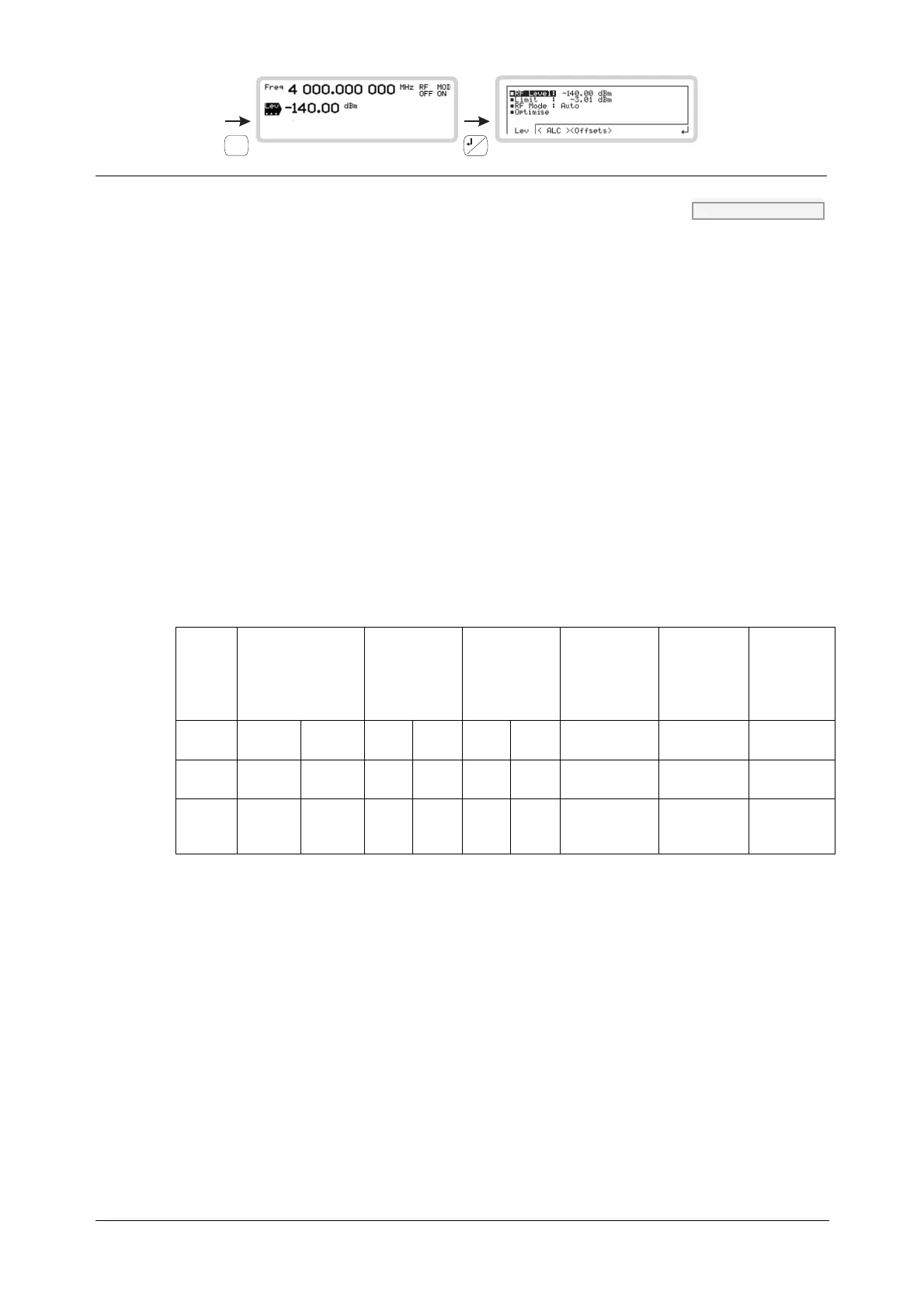
LOCAL OPERATION RF LEVEL
SIG
GEN
B5196
...
B5907
3-26
RF mode POW:OPT page 4-153
A number of RF modes are available, with which you can optimize RF parameters such as
maximum output power, noise floor and linearity of modulation. See the specification in
Chapter 1 for full details of RF optimization modes.
Use the numeric keypad to specify the RF mode in order to optimize the carrier:
0
Auto RF optimization mode is automatically selected on the basis of
requested output power. This can be overridden, as shown
below.
1
Power Gives highest output power consistent with good noise floor
figure and carrier harmonics. IQ/AM linearity is not specified.
2
Noise Gives as good a noise floor figure as the Power mode, still with
reasonable output power. AM with IQ modulation performance
is specified but crest factor/linearity is compromised compared
with ACP mode.
3
ACP Gives optimal IQ linearity consistent with highest possible crest
factor. Small compromise on noise floor/reduced output power.
RF optimization — an illustration (electronic attenuator)
Mode
Auto level
(dBm)
CW/AM/FM/ΦM
Max Min
Auto level
(dBm)
IQ
Max Min
Manual level
(dBm)
Max Min*
Floor noise @
>5 MHz offset
(dBc/Hz)
Linearity
Maximum
crest factor
(dB)
Power +16 +10.01 n/a n/a +16*** -128 <-142,
typically -148
No
requirement
3
Noise +10 -134 +10 +0.01 +10*** -134 <-142,
typically -148
Meets AM
spec.
9
ACP -134.01 -140 0 -140 0 -140 <-140 Meets 3GPP
and TETRA
ACPR spec.
15**
(for carrier frequencies between 10 and 3000 MHz; principle applies throughout frequency range)
* Below these minimum levels the instrument shifts down to the next RF mode to give the
requested output power.
** Higher crest factors (ratio of RMS to peak power) than 15 dB can be supported without
clipping, provided that the external inputs are backed off appropriately from 0.5 V RMS.
*** When IQ modulation is selected, maximum output is reduced by 6 dB below 100 MHz.