134 Chapter 5 Digitizing
this case, a negative percentage of the range (-25%) is used to level trigger
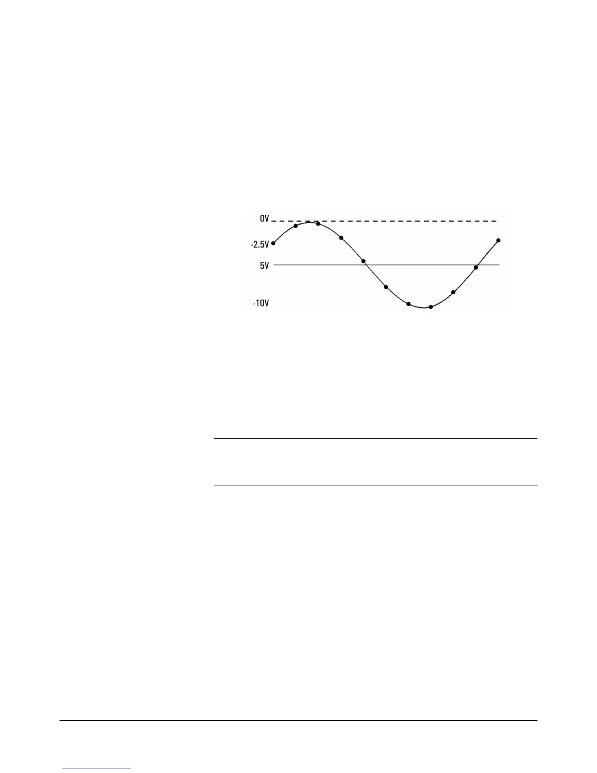
at -2.5V. positive slope.
Figure 29 shows the result.
10OUTPUT 722;"PRESET DIG" !DCV DIGITIZING, 10V RANGE
20OUTPUT 722;"TRIG LEVEL" !LEVEL TRIGGER EVENT
30OUTPUT 722;"SLOPE POS" !TRIGGER ON POSITIVE SLOPE OF SIGNAL
40OUTPUT 722;"LEVEL - 25, DC" !LEVEL TRIGGER AT -25% OF 10V RANGE
45!DC coupled
50 END
Level Filtering When enabled, the level filter function connects a single-pole low-pass filter
circuit to the input of the level-detection circuitry. The low-pass filter has a
3dB point of 75 kHz and prevents high frequency components on the input
signal from causing false triggers. To enable level filtering, send:
OUTPUT 722; "LFILTER ON"
Note The level filter function can also reduce the multimeter’s sensitivity to high
frequency noise for frequency and period measurements or when making
synchronous (SETACV SYNC) ACV or ACDCV measurements.
DCV Digitizing
Digitizing can be done simply by specifying DC voltage measurements with
a short integration time and a short interval between samples ("short" relative
to the frequency of the signal being digitized). This is considered digitizing
although the multimeter’s track-and-hold circuit is not used. The advantages
of DCV digitizing over direct-sampling (discussed later) are a lower noise
level, higher resolution (up to
28 bits), and a maximum sampling rate of 100,000 samples per second
(versus 50,000 for direct-sampling). The disadvantages of DCV digitizing
are a greater amount of trigger jitter (see the Specifications in Appendix A),
the inability to AC-couple the input signal, and a lower bandwidth input path
of 150kHz (vs. 12MHz for direct- or sub-sampling). Since the track-and-hold
circuit is not used for DCV digitizing, each sample is much wider (a minimum
of 500 nanoseconds versus 2 nanoseconds for direct- or sub-sampling).
Figure 29. Level triggering, -25%, pos. slope, DC-coupled