Appendix A Specifications 287
3 / DC Current
DC Current (DCI Function)
Accuracy
3
(ppm Reading + ppm Range)
Range Full Scale
Maximum
Resolution
Shunt
Resistance
Burden
Voltage
Temperature Coefficient
(ppm of Reading + ppm of Range) / °C
Without ACAL
1
With ACAL
2
100 nA 120.000 1 pA 545.2 kW 0.055 V 10+200 2+50
1 µA 1.200000 1 pA 45.2 kW 0.045 V 2+20 2+5
10 µA 12.000000 1 pA 5.2 kW 0.055 V 10+4 2+1
100 µA 120.00000 10 pA 730 W 0.075 V 10+3 2+1
1 mA 1.2000000 100 pA 100 W 0.100 V 10+2 2+1
10 mA 12.000000 1 nA 10 W 0.100 V 10+2 2+1
100 mA 120.00000 10 nA 1 W 0.250 V 25+2 2+1
1 A 1.0500000 100 nA 0.1 W <1.5 V 25+3 2+2
Range 24 Hour
4
90 Day
5
1 Year
5
2 Year
5
100 nA
6
10+400 30+400 30+400 35+400
1 µA
6
10+40 15+40 20+40 25+40
10 µA
6
10+7 15+10 20+10 25+10
100 µA 10+6 15+8 20+8 25+8
1 mA 10+4 15+5 20+5 25+5
10 mA 10+4 15+5 20+5 25+5
100 mA 25+4 30+5 35+5 40+5
1 A 100+10 100+10 110+10 115+10
1. Additional error from
Tcal or last ACAL±1°C.
2. Additional error from
Tcal± 5°C.
3. Specifications are for
PRESET; NPLC 100.
4. Tcal± 1°C.
5. Specifications for 90 day,
1 year, and 2 year are
within 24 hours and ±1°C
of last ACAL; Tcal±5°C
Add 5 ppm of reading
additional error for
Agilent factory
traceability to US NIST.
Traceability error is the
sum of the 10 V and 10
kW traceability values.
6. Typical accuracy.
7. For PRESET; DELAY 0;
DlSP OFF; OFORMAT
DINT; ARANGE OFF.
8. Aperture is selected
independent of line
frequency (LFREQ).
These apertures are for 60
Hz NPLC values where 1
NPLC = 1/ LFREQ. For
50 Hz and NPLC
Indicated, aperture will
increase by 1.2 and
reading rates will decrease
by 0.833.
Settling Characteristics
For first reading or range change error, add .001%
of input current step additional error. Reading
settling times can be affected by source impedance
and cable dielectric absorption characteristics.
Additional Errors
Measurement Considerations
Agilent recommends the use of PTFE cable or other
high impedance, low dielectric absorption cable for low
current measurements. Current measurements at rates
<NPLC 1 are subject to potential noise pickup. Care
must be taken to provide adequate shielding and
guarding to maintain measurement accuracies
Selected Reading Rates
7
Maximum Input
NPLC Aperture Digits Readings / Sec
0.0001 1.4 µs 4.5 2,300
0.0006 10 µs 5.5 1,350
0.01 167 µs
8
6.5 157
0.1 1.67 ms
8
6.5 108
1 16.6 ms
8
7.5 26
10 0.166 s
8
7.5 3
100 7.5 18/min
Rated Input Non-Destructive
I to LO ±1.5 A pk <1.25 A rms
LO to Guard ±200 V pk ±350 V pk
Guard to
Earth
±500 V pk ±1000 V pk
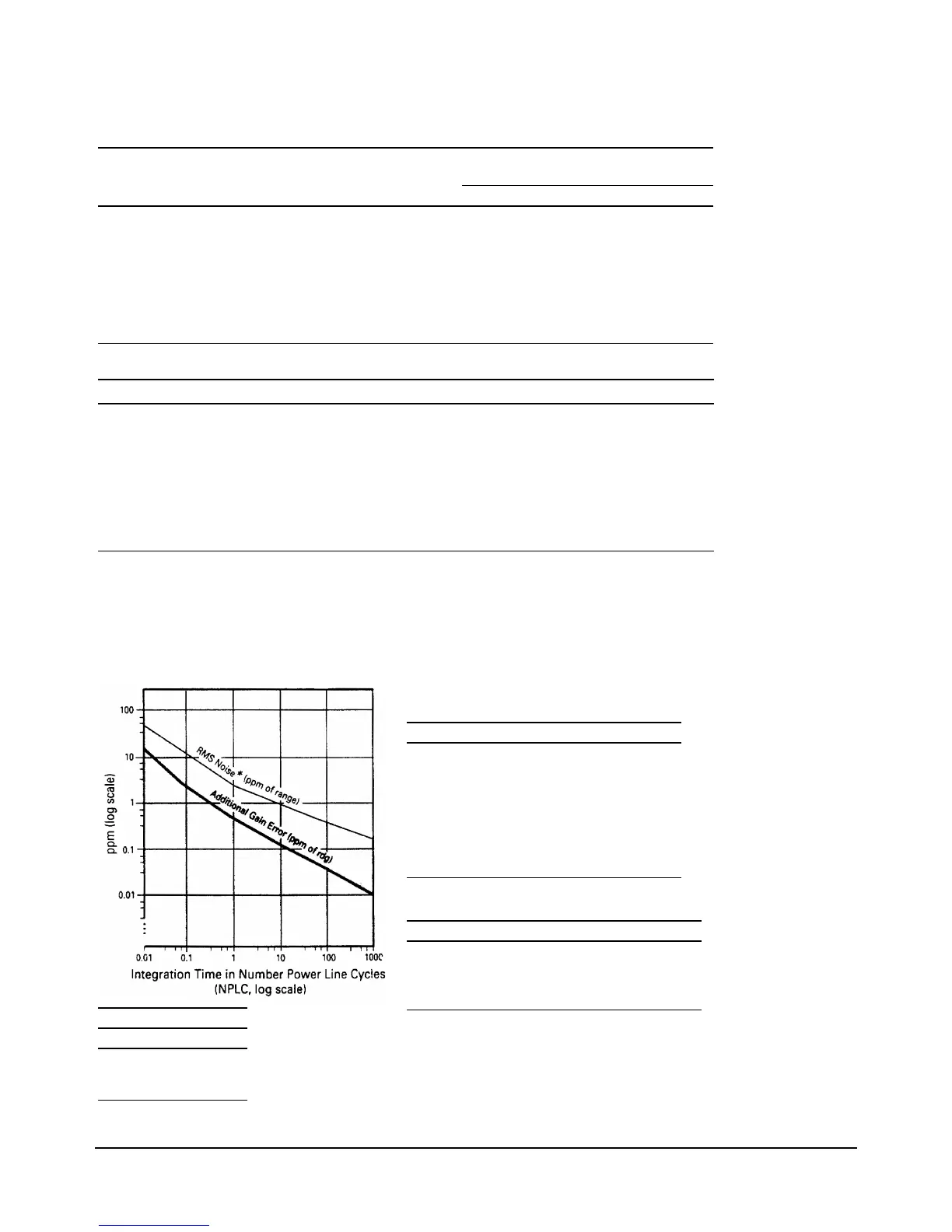
For RMS noise error,
multiply RMS noise result
from graph by multiplier
in chart. For peak noise
error, multiply RMS noise
error by 3.
*RMS Noise
Range Multiplier
100 nA ×100
1 µA ×10
10 µA to 1A ×1