Chapter 3 Configuring for Measurements 63
frequency ranges shown in Table 15. Notice that when measuring AC+DC
voltage using the analog method, for example, any AC components below
10Hz are not included in the measurement.
Note When taking measurements on the 10mV and 100mV ranges using any AC
measurement method, it is possible for radiated noise (such as transients
caused large motors turning on and off) to cause inaccurate readings. For
accurate readings on these ranges, ensure that your nearby environment is
electrically “quiet” and use shielded test leads.
Synchronous Sampling
Conversion
The synchronous sampling conversion calculates the true RMS value from
samples, but requires that the input signal be repetitive (periodic).
Synchronous sampling has excellent, linearity and is the most accurate of the
three methods. Synchronous sampling is useful for measuring periodic
waveforms in the frequency range of 1 Hz to 10 MHz.
Synchronous Sampling
Remarks
• For synchronous sampling, the multimeter uses the LEVEL sync source
event (default mode) to synchronize sampling to the input signal. If the
input signal is removed during a reading and does not return within a certain
amount of time, (the time limits are determined primarily by the AC
bandwidth setting which is discussed later in this section) the measurement
method changes to random sampling so that a measurement can be made.
You can prevent the measurement method from changing using the SSRC
command. You can also pace synchronous sampling to a signal on the Ext
Trig connector using the SSRC command. Refer to the SSRC command
in Chapter 6 for more information and example programs.
• When using the LEVEL sync source, it is possible for noise on the input
signal to produce false level triggers and to cause inaccurate readings. For
accurate readings, ensure that your nearby environment is electrically
"quiet" and use shielded test leads. Enabling level filtering (LFILTER ON
command) reduces the sensitivity to this noise. Refer to the LFILTER
command in Chapter 6 for more information.
• The input signal is always DC-coupled for synchronous sampling
regardless of the specified ACV or ACDCV measurement function. When
ACV is specified, the DC components are mathematically subtracted from
the reading. This is important to consider since the combined AC and DC
voltage levels may cause an overload condition even though the AC voltage
alone normally would not.
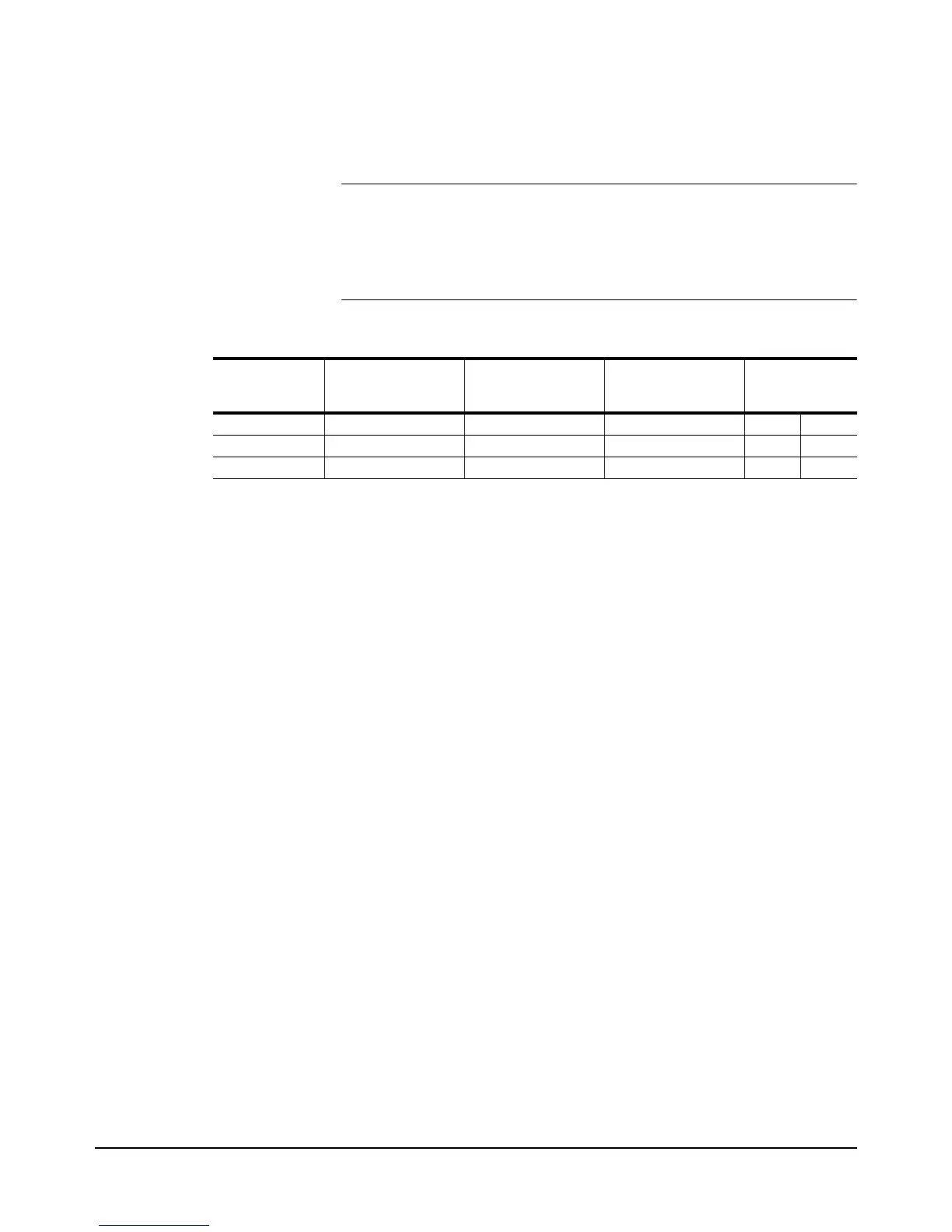
Table 15: AC and AC+DC Voltage Measurement Methods
ACV/ACDCV
Measurement
Method Frequency Range Best Accuracy
Repetitive Signal
Required
Readings Per
Second
Min. Max
Synchronous 1 Hz - 10MHz 0.01% Yes 0.025 10
Analog 10 Hz - 2MHz 0.03% No 0.8 50
Random 20 Hz - 10MHz 0.10% No 0.025 45