34 Chapter 2 Getting Started
Press:
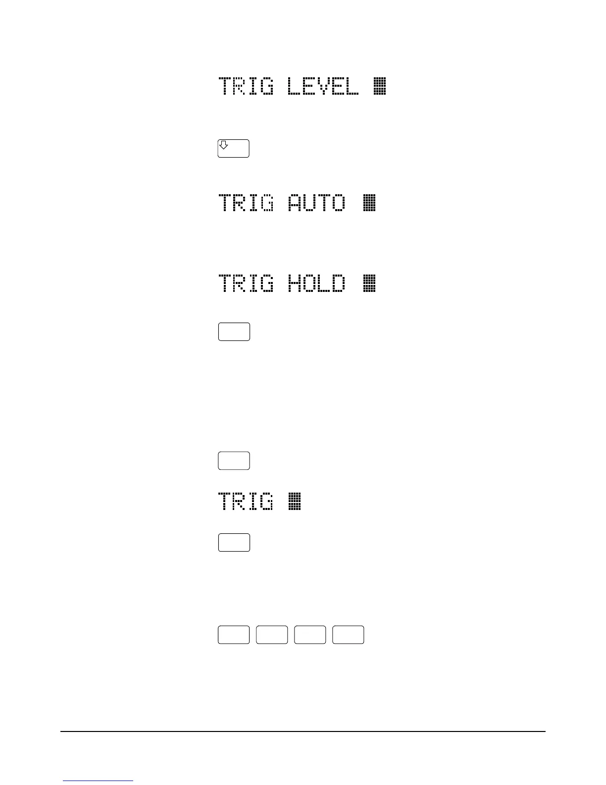
The display shows:
When using the up or down arrow keys, if you step past the last parameter
choice, a wraparound occurs to the other end of the menu. Suppose you want
to suspend triggering. Press the up or down arrow key until the display shows:
Press:
You have now changed the trigger event from auto (power-on state) to HOLD
which causes the multimeter to stop taking readings. (Triggering is discussed
in detail in Chapter 4.)
Default Values Most parameters have a default value. A default value is the value selected
when you execute a command but do not specify a value. For example, the
default value for the trigger parameter is SGL. Press:
Press:
Notice that the multimeter takes one reading and then stops (after the single
trigger, the trigger event becomes HOLD regardless of the previously
specified trigger event). You can also enter-1 to select the default value.
Press:
The multimeter again takes a single reading and then stops.
Numeric Parameters Some commands use numeric parameters, A numeric parameter is the actual
value used by the multimeter. We will use the NPLC configuration key to
Enter
Trig
Enter
Enter
_
1
Enter