EasyManua.ls Logo

Agilent Technologies 3458A User Manual

Agilent Technologies 3458A
372 pages
To Next Page IconTo Next Page
To Previous Page IconTo Previous Page
Page #325 background imageLoading...
Page #325 background image
Appendix D Optimizing Throughout and Reading Rate 325
If NPLC is in the interval from 1 to 10, inclusive, then the NPLC is rounded up
to the next integer. If NPLC > 10, then the actual value of NPLC is rounded up
to the next integer multiple of 10. For values of NPLC <1, the value selected is
used much the same as aperture except that the integration period is scaled in terms
of the line frequency. For example, if the value selected for NPLC is .1 PLC, the
3458A actually sets the integration period to .1X (line period to the nearest 100
ns> or .0016666s (60 Hz operation). The query NPLC? returns 99.9958E-3 PLC.
If the value of 2.5 is selected for NPLC, then the 3458A sets the integration period
to 3 PLC. If the value of 21 is selected for NPLC, then the integration period is
set to 30 PLC. NPLC 0 always selects the shortest integration period possible, 500
ns or 29.99994E-6 PLC(60 HZ operation).
Another command that affects the integration period is the resolution command,
RES, which selects the number of digits of the reading displayed as a function of
a percentage of the maximum input parameter. The resolution of the measurement
is selected as a part of the function command or as the RES command. It sets the
integration period to a value that will allow the ADC to convert the measurement
to the resolution requested.
For example,
DCV,20,.001 !(using the resolution parameter of this command)
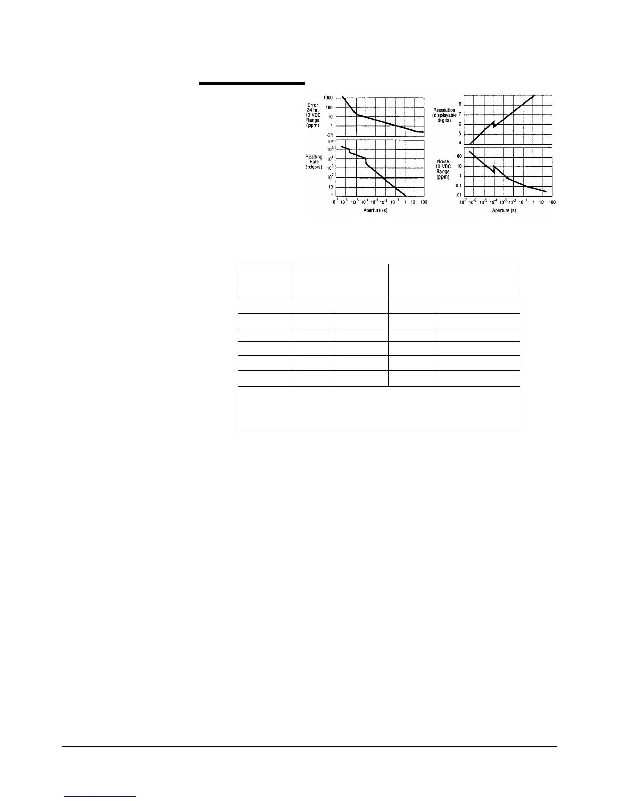
Figure 44. Shows the
dependency of accuracy,
reading rate, resolution,
and noise on aperture
or NPLC selected.
Table 30: Integration time and query response.
Command Integration Time
(APER)
Query Response (NPLC?)
50 Hz 60 Hz 50 Hz 60 Hz
NPLC0 500 ns 500 ns 25 E-6 29.99994 E-6
NPLC.5 10ms 8.333 ms 500 E-3 499.99700 E-3
NPLC 1 20 ms 16.6667 ms 1 1
NPLC10 200 ms 166.667 ms 10 10
NPLC 11
*
200 ms 166.667 ms 20 20
*For NPLC > 10, the continuous integration period is equal to the
integration period ofNPLC 10, but more than one reading is taken.
The resulting average is output to the display or to the GPIB

Table of Contents

Other manuals for Agilent Technologies 3458A

Question and Answer IconNeed help?

Do you have a question about the Agilent Technologies 3458A and is the answer not in the manual?

Agilent Technologies 3458A Specifications

General IconGeneral
Model3458A
ManufacturerAgilent Technologies
CategoryMultimeter
Digits8.5
Sampling Rate100, 000 readings/second
InterfaceGPIB

Summary

Safety Symbols and Warnings

General Safety Precautions (WARNINGS)

Outlines essential safety precautions for operating, servicing, and repairing the product to prevent injury or damage.

Chapter 2 Getting Started

Operating from the Front Panel

Covers using front panel keys, making measurements, changing functions, and controlling display settings.

Operating from Remote

Explains how to control the multimeter remotely via GPIB, including address management and command sending.

Chapter 3 Configuring for Measurements

Configuring for DC or Resistance Measurements

Details how to configure the multimeter for DC voltage, DC current, and 2-wire or 4-wire resistance measurements.

Configuring for AC Measurements

Explains how to configure the multimeter for AC voltage, AC current, frequency, or period measurements.

Chapter 4 Making Measurements

Triggering Measurements

Explains the three-event triggering hierarchy (arm, trigger, sample) and various event choices.

Increasing the Reading Rate

Discusses the multimeter's high-speed mode and factors affecting reading rate and transfer speed.

Math Operations

Explains real-time and post-process math operations, enabling/disabling them, and math registers.

Chapter 5 Digitizing

Digitizing Methods

Details DCV, Direct-Sampling, and Sub-sampling methods, summarizing their characteristics and signal paths.

Level Triggering

Describes how to specify voltage and slope for sampling initiation, with examples for DCV and direct-sampling.

Direct-Sampling

Explains direct-sampling using track-and-hold, its bandwidth, and specifying ranges via max._input parameter.

Sub-Sampling

Covers sub-sampling fundamentals, advantages, and how to specify effective interval and number of samples.

Chapter 6 Command Reference

ACAL

Instructs the multimeter to perform self-calibrations (ALL, DCV, AC, OHMS) and discusses autocalibration security.

PRESET

Configures the multimeter to one of three predefined states: NORM, FAST, or DIG for different operation modes.

SUB

Stores a series of commands as a subprogram, assigning a name for later execution.

TARM

Defines the trigger arm event to enable the trigger event and can be used for multiple measurement cycles.

TEST

Causes the multimeter to perform a series of internal self-tests to check hardware and software integrity.

TRIG

Specifies the trigger event that initiates a measurement, working with TARM and NRDGS.

Chapter 7 BASIC Language for the 3458A

Subprograms

Explains how to store, execute, and manage BASIC language subprograms for system control and automation.

Appendix B GPIB Commands

Appendix C Procedure to Lock Out Front/Rear Terminals and Guard Terminal Switches

Procedure

Outlines the steps for installing the switch lockout kit, including covers and pushrod removal.

Appendix D Optimizing Throughout and Reading Rate

Maximizing the Testing Speed

Covers strategies like tailoring communication paths, program memory, and state storage for optimal testing speed.

DC Volts, DC Current and Resistance

Explains the measurement paths (DCV, track-and-hold) and trade-offs for DC measurements.

AC Volts and AC Current

Details the three ACV measurement techniques (Analog, Synchronous, Random) and their trade-offs.

Optimizing the Testing Process Through Task Allocation

Discusses allocating tasks between the DMM and computer using math functions, memory, and program structure.

Appendix E High Resolution Digitizing With the 3458A

Speed with Resolution

Details the multimeter's flexibility in speed and resolution for audio frequency bandwidth.

Avoiding Aliasing

Provides methods to avoid signal distortion caused by aliasing, ensuring accurate waveform representation.

Choice of Two Measurement Paths

Describes the standard DCV path and the track-and-hold path for digitizing and sampling.

Related product manuals