EasyManua.ls Logo

Agilent Technologies 3458A User Manual

Agilent Technologies 3458A
372 pages
To Next Page IconTo Next Page
To Previous Page IconTo Previous Page
Page #90 background imageLoading...
Page #90 background image
90 Chapter 4 Making Measurements
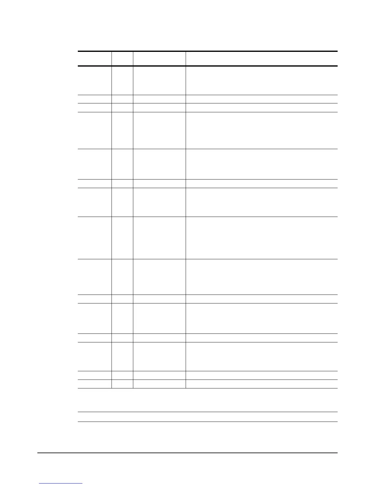
EXT LINE AUTO, EXT, TIMER,
LINE
After a negative edge transition on the Ext Trig input followed
by the power line voltage crossing zero volts, one reading is
taken per sample event until the specified number of readings
are completed.
EXT LINE SYN, LEVEL Illegal
EXT SGL ANY Illegal
EXT SYN SYN After a negative edge transition on the Ext Trig input followed
by the controller requesting data
2
(which satisfies both SYN
events), the first reading is taken. One reading is then taken
per SYN event until the specified number of readings are
completed.
EXT SYN AUTO, EXT, TIMER,
LINE, LEVEL
After a negative edge transition on the Ext Trig input,
followed by the controller requesting data
2
one reading is
taken per sample event, until the specified number of
readings are completed.
HOLD Any Any No readings taken until the trigger arm event is changed.
AUTO, EXT,
SGL, SYN
HOLD Any No readings taken until the trigger event is changed. When
using the SGL trigger arm event and the SYN sample event,
the input buffer must be enabled or you must suppress cr lf
when sending the TARM SGL command.
SGL AUTO Any After executing the TARM SGL command, one reading is
taken per sample event until the specified number of readings
are completed. The trigger arm event then becomes HOLD.
When using the SYN sample event, the input buffer must be
enabled or you must suppress cr lf when sending the TARM
SGL command.
SGL EXT AUTO, EXT, TIMER,
LINE, LEVEL
After executing the TARM SGL command followed by a
negative edge transition on the Ext Trig input, one reading is
taken per sample event, until the specified number of
readings are completed. The trigger arm, event then
becomes HOLD.
SGL EXT SYN Illegal
SGL LEVEL AUTO, EXT, TIMER,
LEVEL
After executing the TARM SGL command followed by the
occurrence of the LEVEL event,
1
one reading is taken per
sample event until the specified number of readings are
completed. The trigger arm event then becomes HOLD.
SGL LEVEL SYN, LINE Illegal
SGL LINE AUTO, EXT, TIMER,
LINE
After executing the TARM SGL command followed by the
power line voltage crossing zero volts, one reading is taken
per sample event until the specified number of readings are
completed. The trigger arm event then becomes HOLD.
SGL LINE SYN, LEVEL Illegal
SGL SGL Any Illegal
Table 21. Event Combinations
Trigger Arm
Event
Trigger
Event
Sample
Event
Description
1
The LEVEL event occures when the specified voltage is reached on the specified slope of the input
signal. The LEVEL trigger event or sample event can only be used for DC voltage or direct-sampled
measurements.
2
The output buffer must be empty and reading memory must be OFF or empty for the SYN event to occur.
3
The input buffer must be enabled or you must suppress cr lf when sending the TARM SGL command.

Table of Contents

Other manuals for Agilent Technologies 3458A

Question and Answer IconNeed help?

Do you have a question about the Agilent Technologies 3458A and is the answer not in the manual?

Agilent Technologies 3458A Specifications

General IconGeneral
Model3458A
ManufacturerAgilent Technologies
CategoryMultimeter
Digits8.5
Sampling Rate100, 000 readings/second
InterfaceGPIB

Summary

Safety Symbols and Warnings

General Safety Precautions (WARNINGS)

Outlines essential safety precautions for operating, servicing, and repairing the product to prevent injury or damage.

Chapter 2 Getting Started

Operating from the Front Panel

Covers using front panel keys, making measurements, changing functions, and controlling display settings.

Operating from Remote

Explains how to control the multimeter remotely via GPIB, including address management and command sending.

Chapter 3 Configuring for Measurements

Configuring for DC or Resistance Measurements

Details how to configure the multimeter for DC voltage, DC current, and 2-wire or 4-wire resistance measurements.

Configuring for AC Measurements

Explains how to configure the multimeter for AC voltage, AC current, frequency, or period measurements.

Chapter 4 Making Measurements

Triggering Measurements

Explains the three-event triggering hierarchy (arm, trigger, sample) and various event choices.

Increasing the Reading Rate

Discusses the multimeter's high-speed mode and factors affecting reading rate and transfer speed.

Math Operations

Explains real-time and post-process math operations, enabling/disabling them, and math registers.

Chapter 5 Digitizing

Digitizing Methods

Details DCV, Direct-Sampling, and Sub-sampling methods, summarizing their characteristics and signal paths.

Level Triggering

Describes how to specify voltage and slope for sampling initiation, with examples for DCV and direct-sampling.

Direct-Sampling

Explains direct-sampling using track-and-hold, its bandwidth, and specifying ranges via max._input parameter.

Sub-Sampling

Covers sub-sampling fundamentals, advantages, and how to specify effective interval and number of samples.

Chapter 6 Command Reference

ACAL

Instructs the multimeter to perform self-calibrations (ALL, DCV, AC, OHMS) and discusses autocalibration security.

PRESET

Configures the multimeter to one of three predefined states: NORM, FAST, or DIG for different operation modes.

SUB

Stores a series of commands as a subprogram, assigning a name for later execution.

TARM

Defines the trigger arm event to enable the trigger event and can be used for multiple measurement cycles.

TEST

Causes the multimeter to perform a series of internal self-tests to check hardware and software integrity.

TRIG

Specifies the trigger event that initiates a measurement, working with TARM and NRDGS.

Chapter 7 BASIC Language for the 3458A

Subprograms

Explains how to store, execute, and manage BASIC language subprograms for system control and automation.

Appendix B GPIB Commands

Appendix C Procedure to Lock Out Front/Rear Terminals and Guard Terminal Switches

Procedure

Outlines the steps for installing the switch lockout kit, including covers and pushrod removal.

Appendix D Optimizing Throughout and Reading Rate

Maximizing the Testing Speed

Covers strategies like tailoring communication paths, program memory, and state storage for optimal testing speed.

DC Volts, DC Current and Resistance

Explains the measurement paths (DCV, track-and-hold) and trade-offs for DC measurements.

AC Volts and AC Current

Details the three ACV measurement techniques (Analog, Synchronous, Random) and their trade-offs.

Optimizing the Testing Process Through Task Allocation

Discusses allocating tasks between the DMM and computer using math functions, memory, and program structure.

Appendix E High Resolution Digitizing With the 3458A

Speed with Resolution

Details the multimeter's flexibility in speed and resolution for audio frequency bandwidth.

Avoiding Aliasing

Provides methods to avoid signal distortion caused by aliasing, ensuring accurate waveform representation.

Choice of Two Measurement Paths

Describes the standard DCV path and the track-and-hold path for digitizing and sampling.

Related product manuals