Chapter 8 Ensuring Repeatability, Accuracy, and Resolution
Ensuring Accuracy
8-10 Getting Started Guide
8
Correcting for slope
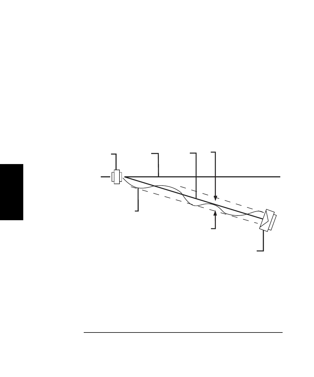
The misalignment (slope) between the machine travel and the laser
measurement axis for a straightness measure is different from the cosine
error that you get in linear measurements. Misalignment causes a slope to
be measured because the reflector is not directing its reference bisector
along a path parallel to the machine travel axis (Figure 8–5).
You can have the Agilent 10747F software automatically adjust for the
effects of slope on your measurement.
Figure 8-5. Example of slope in a straightness measurement
To have the software adjust for slope, follow these steps:
1 Go to the Set Up Graph screen.
2 If necessary, turn on the slope correction feature by selecting it.
3 Select the slope correction method supported by your industrial standard.
1
Interferometer
2 Reference bisector
3 Machine travel
4 True out-of-straightness
distance
5 Straightness reflector
6 Data path
4
5
4
321
6
 Loading...


