Chapter 8 Ensuring Repeatability, Accuracy, and Resolution
Ensuring Accuracy
Getting Started Guide 8-7
8
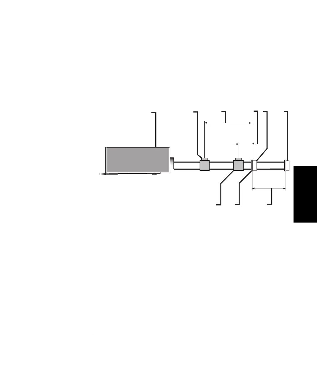
To minimize this error, during setup you should place the optics as close
as possible without allowing them to touch. Measure the remaining
distance and enter and record this distance on the Set Up Laser screen so
the system can compensate for WOL changes over this distance.
Figure 8-3. Example of deadpath error
Cosine error
Cosine error results when the laser beam path and the desired
measurement axis are not parallel (Figure 8-4). When the laser path is not
properly aligned with the machine travel, the laser beam travels at an
angle to the actual machine travel.
As a result, the recorded measurement is shorter than the actual distance
the machine traveled. The error increases as the angle or distance grows.
1
Laser head
2 Interferometer
assembly
3 Deadpath distance for
first interferometer
position
4 Deadpath distance for
second interferometer
position
5 Linear retroreflector at
the zero point
6 Linear retroreflector at
measurement point x
7 Measurement length
8 Zero point of
measurement
9 Interferometer
assembly placed to
minimize the
deadpath error
1
2
3
4
5
6
7
8
9
 Loading...


