216 Agilent 1290 Infinity Binary Pump User Manual
12 Hardware Information
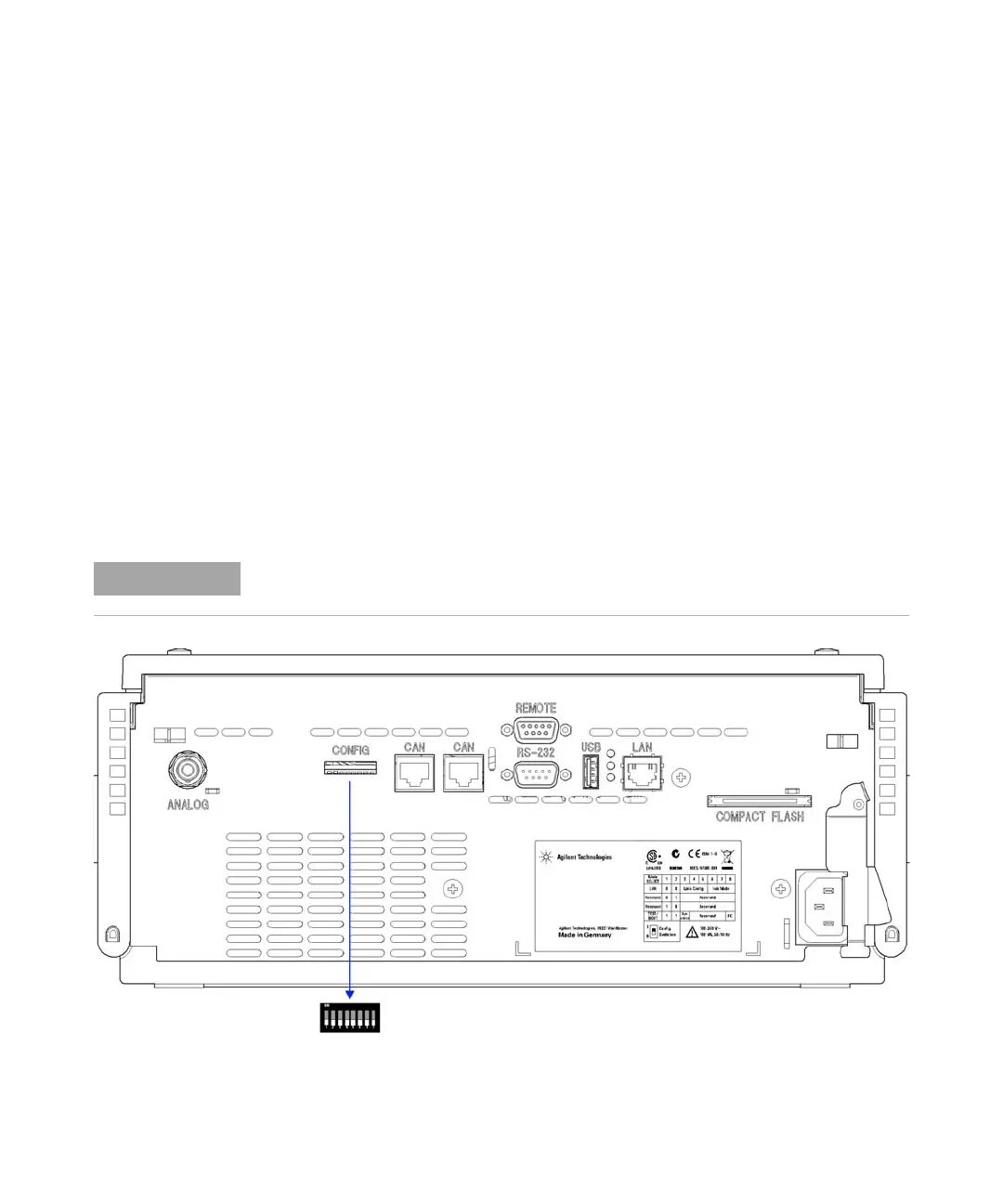
Setting the 8-bit Configuration Switch
Setting the 8-bit Configuration Switch
The 8-bit configuration switch is located at the rear of the module. Switch
settings provide configuration parameters for LAN, serial communication
protocol and instrument specific initialization procedures.
All modules with on-board LAN, e.g. G1315/65C/D, G1314D/E/F, G4212A/B,
G4220A/B:
• Default is ALL switches DOWN (best settings).
• Bootp mode for LAN and
• 19200 baud, 8 data bit / 1 stop bit with no parity for RS-232
• For specific LAN modes switches 3-8 must be set as required.
• For boot/test modes switches 1+2 must be UP plus required mode.
Figure 33 Location of Configuration Switch (example shows a G4212A DAD)
For normal operation use the default (best) settings.