194 Agilent 1290 Infinity Binary Pump User Manual
11 Identifying Cables
Remote Cables
Remote Cables
One end of these cables provides a Agilent Technologies APG (Analytical
Products Group) remote connector to be connected to Agilent modules. The
other end depends on the instrument to be connected to.
Agilent Module to 3396A Integrators
Agilent Module to 3396 Series II / 3395A Integrators
Use the cable Agilent module to 3396A Series I integrators (03394-60600) and
cut pin #5 on the integrator side. Otherwise the integrator prints START; not
ready.
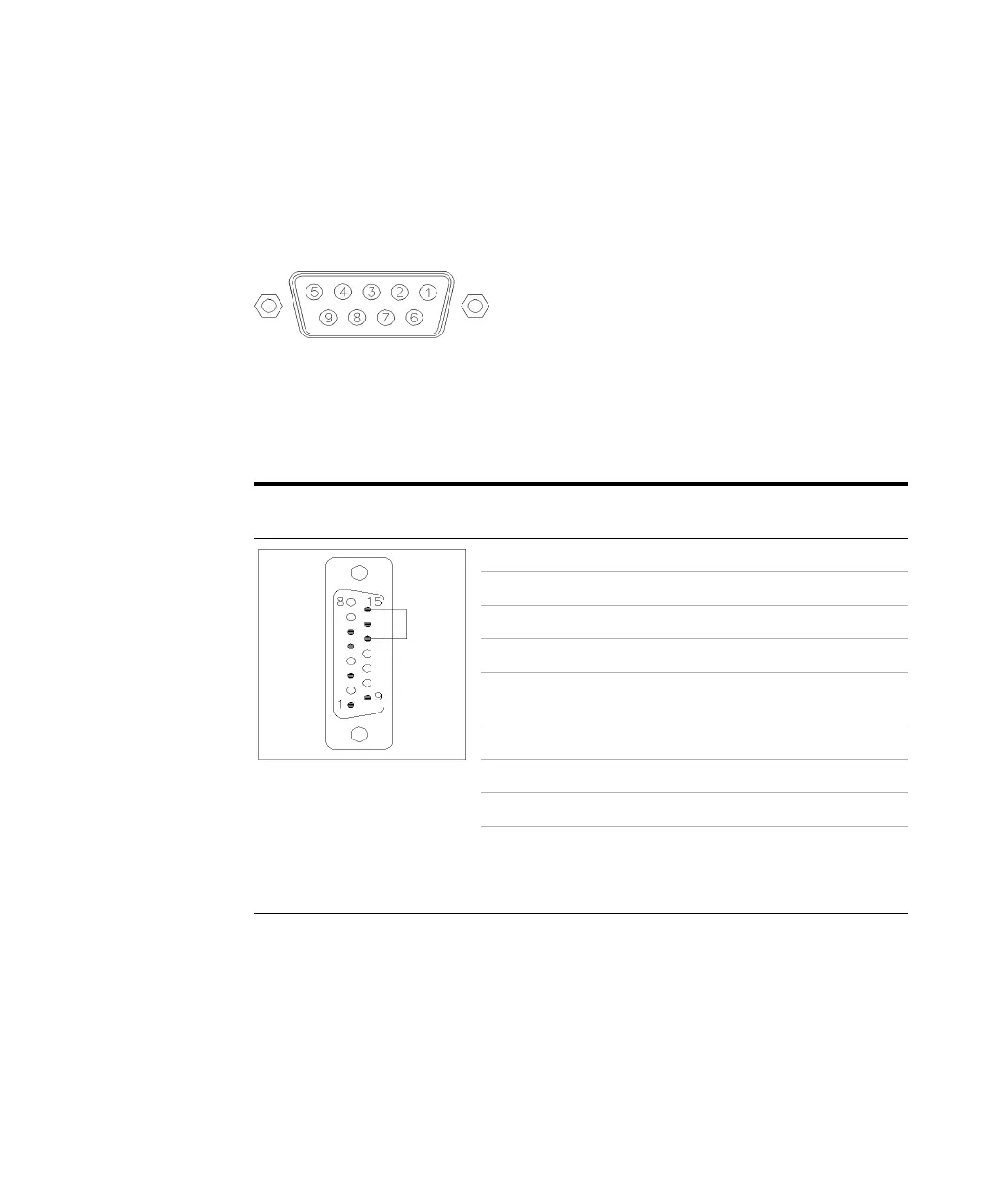
p/n 03394-60600 Pin 3396A Pin Agilent
module
Signal Name Active
(TTL)
9 1 - White Digital ground
NC 2 - Brown Prepare run Low
3 3 - Gray Start Low
NC 4 - Blue Shut down Low
NC 5 - Pink Not
connected
NC 6 - Yellow Power on High
5,14 7 - Red Ready High
18 - GreenStopLow
NC 9 - Black Start request Low
13, 15 Not
connected