Rockwell Automation Publication 1756-UM535D-EN-P - November 2012 91
Configure the EtherNet/IP Network Chapter 4
Complete these steps to construct and configure the example DLR network.
1. Install and connect devices on the DLR network but leave at least one
connection open.
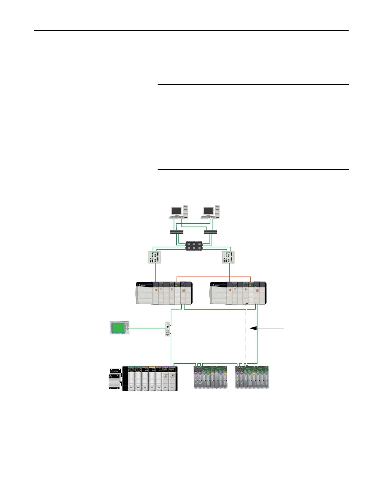
This graphic shows the DLR network with one connection left open.
Figure 25 - DLR Topology with One Connection Unmade
When you initially install and connect devices on the DLR network,
leave at least one connection open, that is, temporarily omit the
physical connection between two nodes on the DLR network.
You must configure an active supervisor node for the network before
network operation begins when the final connection is made.
If you fully connect your DLR network without a supervisor configured,
a network storm can result, rendering the network unusable until one
link is disconnected and at least one supervisor is enabled.
Stratix 8000 Switches
Redundant Chassis Pair
HMI Connected via
1783-ETAP Taps
Remote ControlLogix Chassis with Redundant Power
Supplies and I/O Modules
1715 Redundant I/O System
Cisco Switch
FactoryTalk Application
Physical
connection is not
made yet.
 Loading...

