122 Rockwell Automation Publication 2097-UM001D-EN-P - November 2012
Chapter 5 MotionView Software Configuration
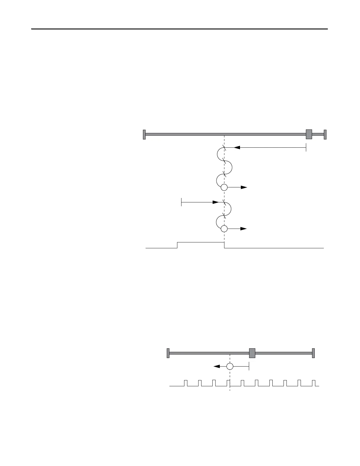
The axis accelerates to slow-homing velocity in the rightward direction. Motion
continues until the falling-edge of the homing switch is detected (position 29).
This is the home position (excluding offset).
Figure 71 - Homing Method 29
Homing Method 33
Using this method, the initial direction of movement is reverse. The home
position is the first index pulse past the shaft starting position. The axis
accelerates to fast-homing velocity in the reverse direction and continues until
the rising-edge of the first index pulse (position 33) is detected.
Figure 72 - Homing Method 33
If the axis is on the wrong side of the homing switch when homing is started,
the axis moves reverse until it contacts the negative limit switch (A1). Upon
activating the negative limit switch the axis will change direction (forward)
following the procedure as detailed above, but ignoring the initial move in the
reverse direction.
29
A
B
C
B
C
29

 Loading...


