Rockwell Automation Publication 2097-UM001D-EN-P - November 2012 93
MotionView Software Configuration Chapter 5
Input/Output Categories
The Input/Output categories provide access to the configuration of the
modifiable Digital I/O and Analog I/O parameters.
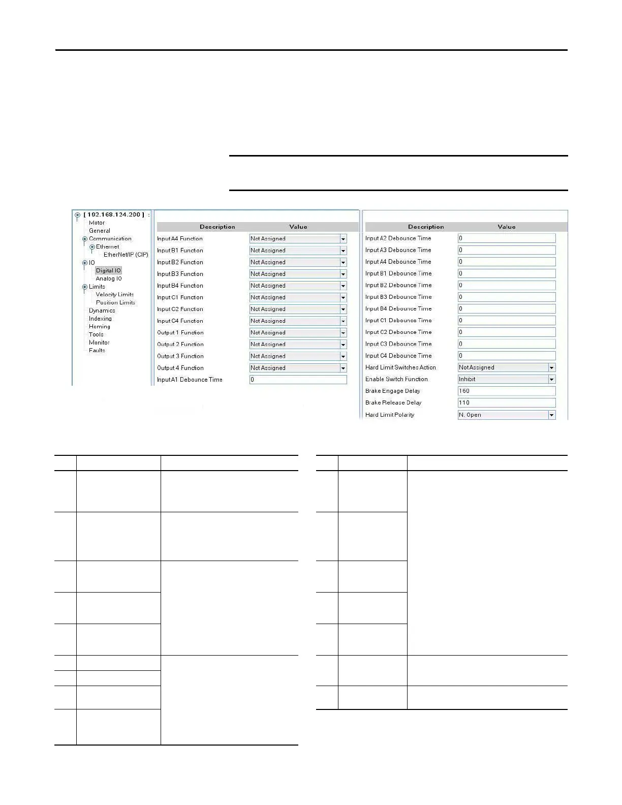
Digital I/O
Table 43 - Digital I/O Category
Drive object parameters of type DINT can be used only in the RAM integer data
links, parameters of type REAL can be used only in the RAM float data links.
ID Parameter Name Description ID Parameter Name Description
29 Enable Switch Function Configuration of the enable digital input A3.
0 = Inhibit only. Must be asserted before the drive
can be enabled.
1 = Run. Enables drive when asserted.
624 Input A4 Function Configuration of the specific function for the individual digital
inputs, pre-assigned inputs such as Enable and Registration
are not configurable.
1 = Abort Index
2 = (Reserved)
3 = Start Index
4 = Define Home
5 = Abort Homing
6 = Start Homing
7 = Fault Reset
8 = Index Select 0
9 = Index Select 1
10 = Index Select 2
11 = Index Select 3
12 = Index Select 4
Configure Home Sensor input from Homing Category.
84 Hard Limit Switches Action Configuration of the action to take when the limit
switches are asserted.
0 = Not used
1 = Disable and coast
2 = Ramped Decel and Disable
625
…
628
Input B1…B4 Function
189
…
192
Input A1…A4
de-bounce time
Debounce time (0…1000 ms) of the individual
digital inputs.
629 Input C1 Function
193
…
196
Input B1…B4
de-bounce time
630 Input C2 Function
197
…
200
Input C1…C4
de-bounce time
631 Input C4 Function
201 Output 1 Function (OUT1) Configuration of the specific function for the
individual digital outputs.
0 = Not Assigned
1 = Zero Speed
2 = In Speed Window
3 = Current Limit
4 = Run time fault
5 = Ready
6 = Brake
7 = In position
651 Brake Engage Delay Time (ms) from when the drive is disabled to the time that
motion is stopped and brake is engaged.
202 Output 2 Function (OUT2)
203 Output 3 Function (OUT3) 652 Brake Release Delay Time (ms) from when the drive is enabled to the time that
motion is allowed to begin (brake is released).
204 Output 4 Function (OUT4)

 Loading...


