Rockwell Automation Publication 2097-UM001D-EN-P - November 2012 45
Kinetix 300 Drive Connector Data and Feature Descriptions Chapter 3
Digital Outputs
There are five digital outputs, OUT1…OUT4 and RDY, available on the IOD
connector. Outputs are optically isolated open collector/emitter and are fully
isolated from the drive circuits. Each output, OUT1…OUT4, can be assigned to
one of these functions:
• Not assigned
• Zero speed
• In-speed window
• Current limit
• Run-time fault
• Ready
• Brake (motor brake release)
The Ready Output has a fixed function that becomes active when the drive is
enabled and the output power transistors become energized.
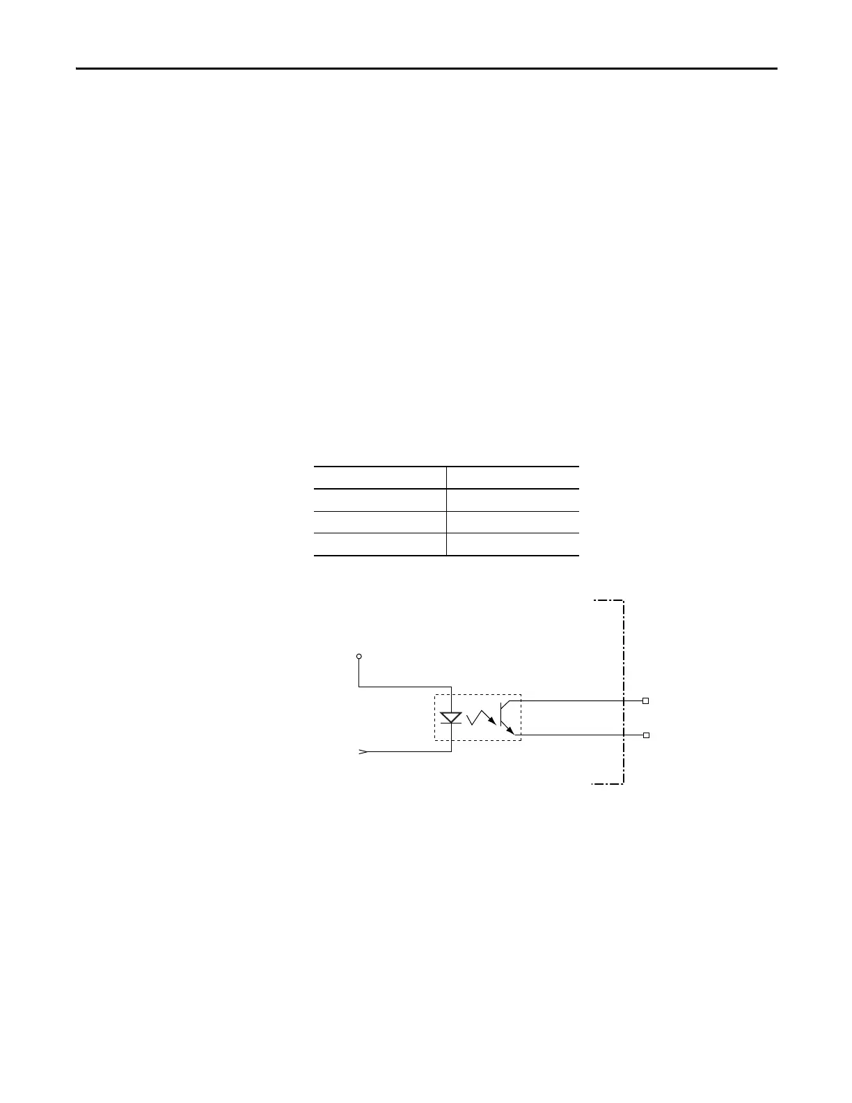
Table 11 - Digital Output Signal Specifications
Figure 20 - Digital Output Circuit
Parameter Value
Scan time 500 μs
Current, max 100 mA
Voltage, max 30V DC
OUT1-E
OUT1-C
Logic Power
GND

 Loading...


