Rockwell Automation Publication 2097-UM001D-EN-P - November 2012 47
Kinetix 300 Drive Connector Data and Feature Descriptions Chapter 3
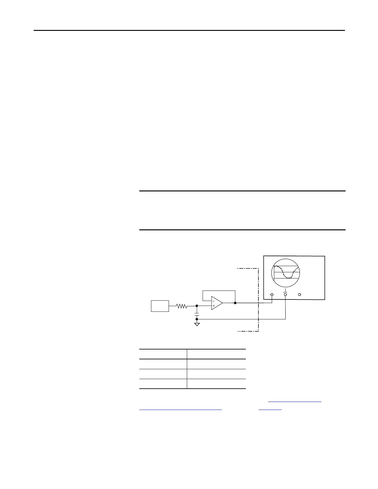
Analog Output
The analog output (AO) on pin IOD-23 has a 10-bit resolution. The analog
output is a single-ended signal with reference to Analog Common (ACOM) that
can represent this motor data:
• Not Assigned
• RMS Phase Current
• RMS Peak Current
• Motor Velocity
• Phase Current U
• Phase Current V
• Phase Current W
• Iq Current
• Id Current
Figure 21 - Analog Output Circuit
Table 13 - Analog Output Specifications
For configuration/setup of the analog outputs, see Configure the Drive
Parameters and System Variables beginning on page 145.
Output values can vary during powerup until the specified power supply
voltage is reached.
MotionView software refers to Phase Current U, V, and W as R, S, and T
respectively.
CH1
CH2
DAC
Parameter Value
Scan time 0.0625 ms
Current, max 10 mA
Voltage range -10…10V DC

 Loading...


