172 Rockwell Automation Publication 2097-UM001D-EN-P - November 2012
Appendix A Interconnect Diagrams
Interconnect Diagram Notes
This appendix provides wiring examples to assist you in wiring the Kinetix 300
system. The notes below apply to the wiring examples on the pages that follow.
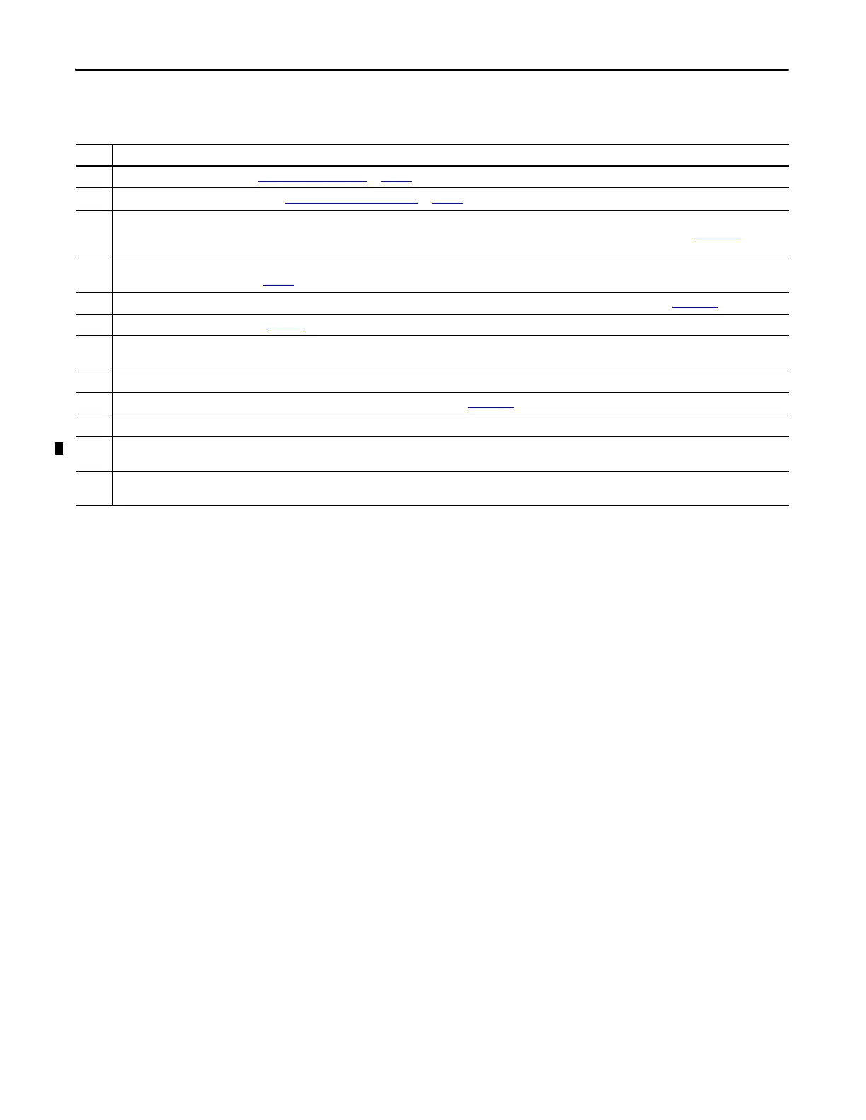
Note Information
1 For power wiring specifications, see Power Wiring Requirements
on page 65.
2 For input fuse and circuit breaker sizes, see Circuit Breaker/Fuse Specifications
on page 22.
3 Place the AC (EMC) line filters as close to the drive as possible and do not route very dirty wires in the wireway. If routing in wireway is unavoidable, use shielded cable with
shields grounded to the drive chassis and filter case. For AC line filter specifications, see Kinetix Servo Drives Specifications Technical Data, publication GMC-TD003
. This filter
does not apply to 2097-V32PRx drives because they have integrated AC line filters.
4 Terminal block is required to make connections. Configure one pair from the Digital OUT-1… OUT-4, pins 43…50, as Brake in MotionView software. For Digital Output
specifications, see Digital Outputs on page 45
.
5 Contactor coil (M1) needs integrated surge suppressors for AC coil operation. See Kinetix Servo Drives Specifications Technical Data, publication GMC-TD003
.
6 See the Motor Brake Currents table on page 185
to size the interposing relay for your application.
7 Drive Enable input must be opened when main power is removed, or a drive fault occurs. A delay of at least 1.0 second must be observed before attempting to enable the
drive after main power is restored.
8 Cable shield clamp must be used to meet CE requirements. No external connection to ground is required.
9 For motor cable specifications, see the Kinetix Motion Control Selection Guide, publication GMC-SG001
.
10 Motor power cables (2090-XXNPMF-xxSxx and 2090-CPBM6DF-16AAxx) have a drain wire that must be folded back under the cable shield clamp.
11 LDAT-xxxxxxB, MPL-Axxx, MPM-Axxx, MPF-Axxx, MPS-Axxx, MPAR-Axxx, MPAI-Axxx, and MPAS-Axxx, encoders use the +5V DC supply. LDAT-xxxxxxD, MPL-Bxxx, MPM-Bxxx,
MPF-Bxxx, MPS-Bxxx, MPAR-Bxxx, MPAI-Bxxx, and MPAS-Bxxx, encoders use +9V DC.
12 Brake connector pins are labeled plus (+) and minus (-) or F and G respectively. Power connector pins are labeled U, V, W, and GND or
A, B, C, and D respectively.

 Loading...


