Rockwell Automation Publication 2097-UM001D-EN-P - November 2012 37
Kinetix 300 Drive Connector Data and Feature Descriptions Chapter 3
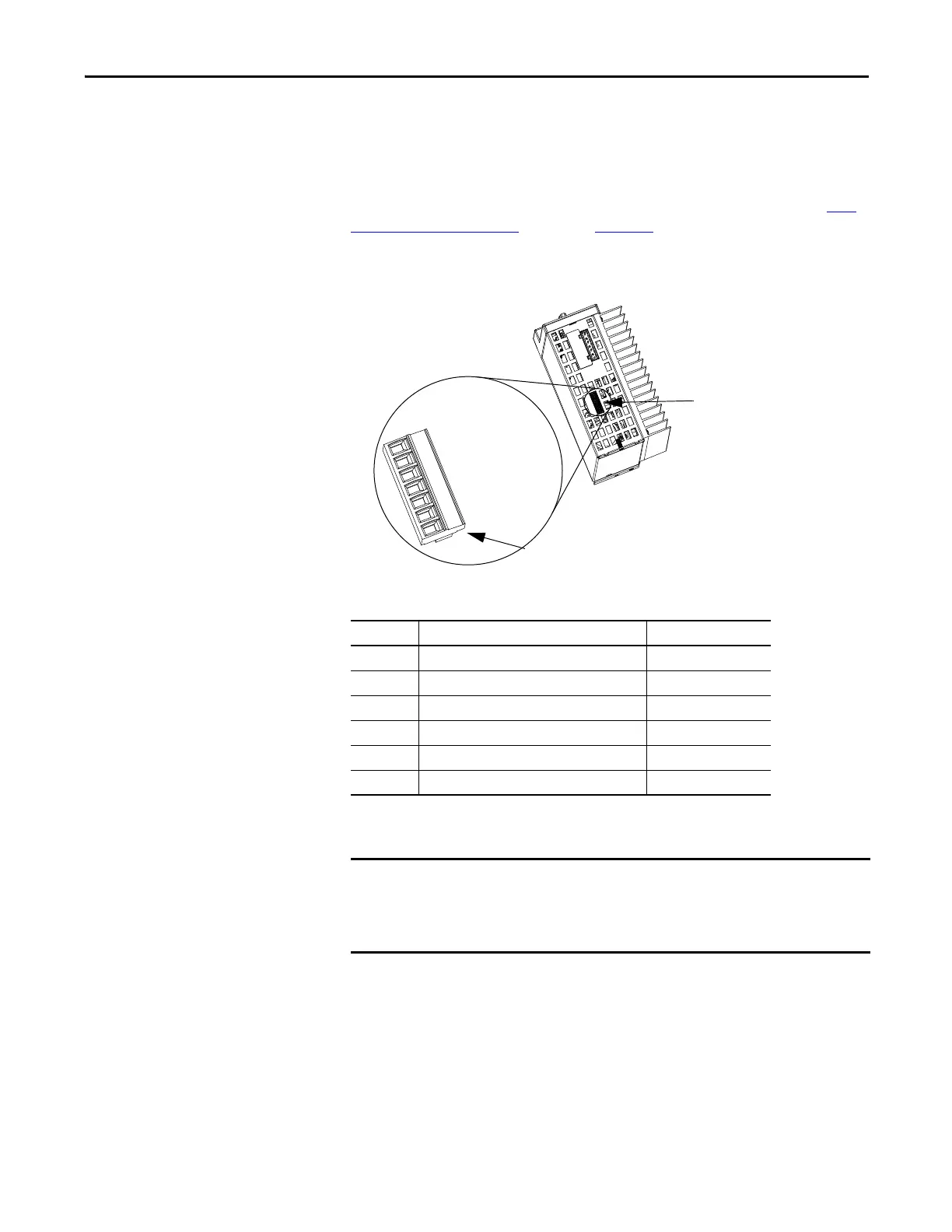
Safe Torque-off Connector Pinout
The Kinetix 300 drive ships with the (6-pin) wiring-plug header that connects
your safety circuit to the Kinetix 300 drive safe torque-off (STO) connector. If
your system does not use the safe torque-off feature, follow instructions in Safe
To r q u e - o f f F e a t u r e By p a s s starting on page 166 to wire the drive with motion-
allowed jumpers.
Figure 10 - Safe Torque-off Connector
Table 8 - Kinetix 300 Drive Safe Torque-off Connector Pinout
1 2 3 4 5 6
+24 V DC control
Control COM
Safety status
Safety input 1
Safety COM
Safety input 2
Bottom view of the Kinetix 300 drive.
(2097-V33PR5 drive is shown)
Wiring Plug Header
Safe Torque-off
(STO) Connector
STO Pin Description Signal
1 +24V DC output from the drive +24V DC control
2 +24V DC output common Control COM
3 Safety status Safety Status
4 Safety input 1 (+24V DC to enable) Safety Input 1
5 Safety common Safety COM
6 Safety input 2 (+24V DC to enable) Safety Input 2
Pins STO-1 (+24V DC Control) and STO-2 (Control COM) are used only by the
motion-allowed jumpers to defeat the safe torque-off function. When the safe
torque-off function is in operation, the 24V supply must come from an external
source.

 Loading...


