168 Rockwell Automation Publication 2097-UM001D-EN-P - November 2012
Chapter 8 Kinetix 300 Drive Safe Torque-off Feature
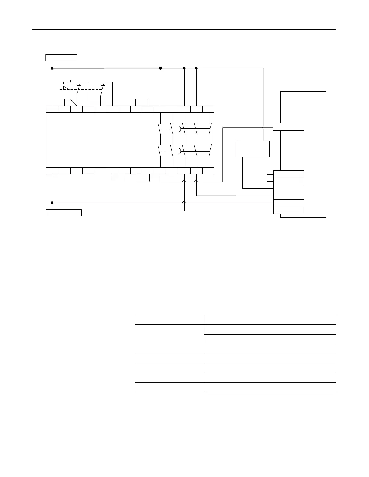
Figure 80 - Single-axis Relay Configuration (Stop Category 1) with Automatic Reset
(1) The digital input, configured for Abort Index in MotionView software, must be active-high when the safety function is requested, so
an interposing relay may be required to invert the signal. Digital input common (IN_x_COM) must be used in this signal activation/
de-activation transition.
You can also bring this input into a PLC where you can use an AOP (add on profile) or assembly object to activate the recommended
digital input (abort index).
Safe Torque-off Signal
Specifications
This table provides specifications for the safe torque-off signals used in the
Kinetix 300 servo drives.
A1 S52 S11 S12 S21 S22 S33 S34 13 23 37 47 57
A2 X1 X2 X3 X4 Y39 Y40 Y2 Y1 14 24 38 48 58
+24V DC
COM
Status
Safety Input 1
Safety Common
Safety Input 2
1
2
3
4
5
6
Allen-Bradley Monitoring Safety Relay
MSR138DP (440R-M23151)
External 24V COM
Safe Torque-off
External +24V DC
Kinetix 300 Drive
Safe Torque-off
(STO) Connector
I/O
(IOD) Connector
Auxiliary Signal
to PLC
Digital Input
(1)
Pins 1 and 2 are not used when using Safety Inputs.
Pin 3 is a sinking output.
Attribute Value
Safety inputs
(1)
(1) Safety inputs are not designed for pulse testing.
Insulated, compatible with single-ended output (+24V DC)
Enable voltage range: 20…24V DC
Disable voltage range: 0…1.0V DC
Input impedance 6.8 k Ω
Safety status Isolated Open Collector (Emitter is grounded.)
Output load capability 100 mA
Digital outputs max voltage 30V DC

 Loading...


