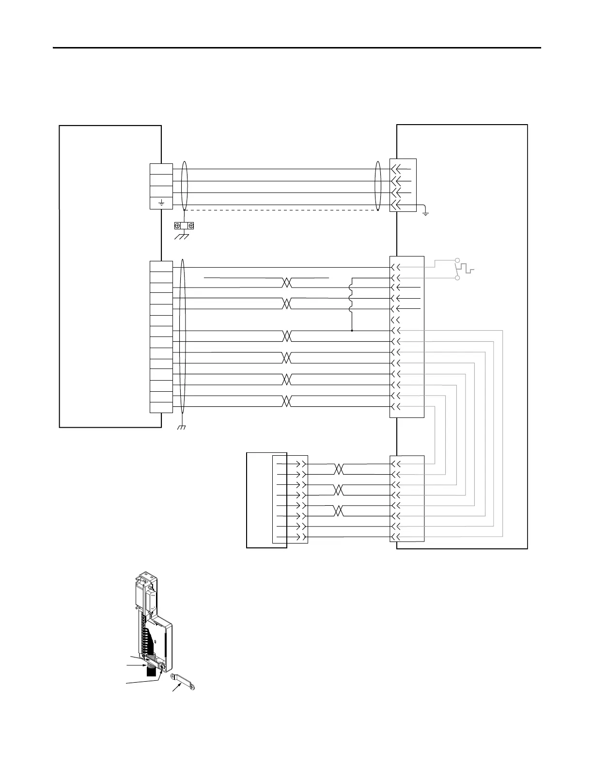
EasyManua.ls Logo

Allen-Bradley Kinetix 300 - Kinetix 300 Drive;Linear Motor Wiring Examples

Allen-Bradley Kinetix 300
230 pages
To Next Page IconTo Next Page
To Previous Page IconTo Previous Page
Loading...
Rockwell Automation Publication 2097-UM001D-EN-P - November 2012 179
Interconnect Diagrams Appendix A
Kinetix 300 Drive/Linear
Motor Wiring Examples
These wiring diagrams apply to Kinetix 300 drives with compatible linear
motors.
Figure 90 - Kinetix 300 Drive with LDC-Series and LDL Linear Motors
A
B
C
AM+
AM-
BM+
BM-
IM+
IM-
+5VDC
ECOM
BM+
BM-
IM+
IM-
+5V DC
ECOM
TS-
N/C
N/C
TS+
S3
S2
S1
Green
White/Green
Gray
WHT/Gray
Blue
WHT/Blue
Yellow
WHT/Yellow
WHT/Orange
Red
WHT/Red
AM+
AM-
Black
WHT/Black
4
3
2
1
Green/Yellow
Blue
Black
Brown
GND
W
V
U
10
9
6
5
3
4
2
1
1
4
2
5
3
6
8
7
15
13
14
16
17
1
2
3
4
5
10
14
6
11
12
13
8
Motor Power
(MP) Connector
2097-V3xPRx
Kinetix 300 Drives
Motor Feedback
(MF) Connector
Three-phase
Motor Power
Motor
Feedback
Thermal Sensor
TTL Encoder
See low profile connector illustration
(lower left) for proper grounding and
shield termination techniques.
Low Profile Connector
(2090-K2CK-D15M shown)
Grounding Technique for
Feedback Cable Shield
Turn clamp over to hold
small cables secure.
Exposed shield secured
under clamp.
Clamp Screws (2)
Clamp
LDC-Series and LDL-Series
Linear Motor Coil
2090-XXNFMF-Sxx (standard) or
2090-CFBM7DF-CDAFxx (continuous-flex)
(flying-lead) Feedback Cable
Notes 9,
2090-CPWM7DF-xxAAxx (standard)
or 2090-CPWM7DF-xxAFxx (continuous-flex)
Motor Power Cable
Notes 9, 10

Table of Contents

Related product manuals