52 Rockwell Automation Publication 2097-UM001D-EN-P - November 2012
Chapter 3 Kinetix 300 Drive Connector Data and Feature Descriptions
Motor Feedback Specifications
The Kinetix 300 drives support multiple types of feedback devices by using the
15-pin (MF) motor feedback connector and sharing connector pins in many
cases.
Table 18 - Motor Feedback Signals by Device Type
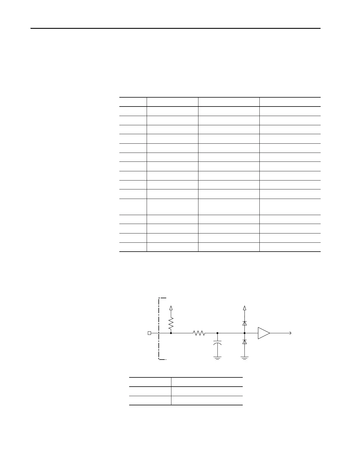
This is the motor thermostat interface schematic. Although the thermostat signal
is shown for all feedback types, some motors may not support this feature because
it is not part of the feedback device.
Figure 25 - Motor Thermostat Interface
Table 19 - Motor Thermostat State Specifications
MF Pin SICK-Stegmann Hiperface Generic TTL Incremental Tamagawa 17-bit Serial
1SIN+ AM+ —
2SIN- AM- —
3COS+ BM+ —
4COS- BM- —
5 DATA+ IM+ DATA+
6 ECOM ECOM ECOM
7EPWR9V — —
8— S3 —
9— — —
10 DATA- IM- DATA-
11 TS TS —
12 — S1 —
13 — S2 —
14 — EPWR5V EPWR5V
15 — — —
+5V
1 k
W
6.81 k
W
0.01 µ
F
MTR_TS
+5V
State Resistance at TS
No Fault 500 Ω
Fault 10 kΩ

 Loading...


