Rockwell Automation Publication 2097-UM001D-EN-P - November 2012 53
Kinetix 300 Drive Connector Data and Feature Descriptions Chapter 3
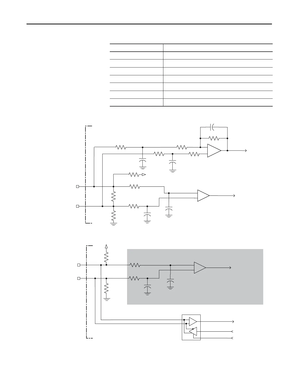
Table 20 - SICK-Stegmann Hiperface Specifications
Figure 26 - SICK-Stegmann Hiperface Interface, SIN and COS Signals
Figure 27 - SICK-Stegmann Hiperface Interface, DATA Signals
Attribute Value
Protocol Hiperface
Memory support Not programmed, or programmed with Allen-Bradley motor data
Hiperface data communication RS485, 9600 baud, 8 data bits, no parity
Sine/Cosine interpolation 2048 counts/sine period
Input frequency (AM/BM) 250 kHz, max
Input voltage (AM/BM) 0.6...1.2V, p-p, measured at the drive inputs
Line loss detection (AM/BM) Average (sin
2
+ cos
2
) > constant
56 pF
SIN+ or
COS+
SIN- or
COS-
+
1 k
W
-
to AqB Counter
1 k
W
10 k
W
10 k
W
1 k
W
1 k
W
1 k
W
56 pF
56 pF
26.7 k
W
47 pF
to A/D Converter
56 pF
+5V
1 k
W
+
-
1 k
W
+
to UART
from UART
from UART
DATA+
DATA-
10 k
W
to AqB Counter
1 k
W
1 k
W
10
W
56 pF
56 pF
+5V
-
Kinetix 300 Drive
Shaded area indicates components that are part of the circuit, but support
other feedback device types (not used for SICK-Stegmann Hiperface support).

 Loading...


