174 Rockwell Automation Publication 2097-UM001D-EN-P - November 2012
Appendix A Interconnect Diagrams
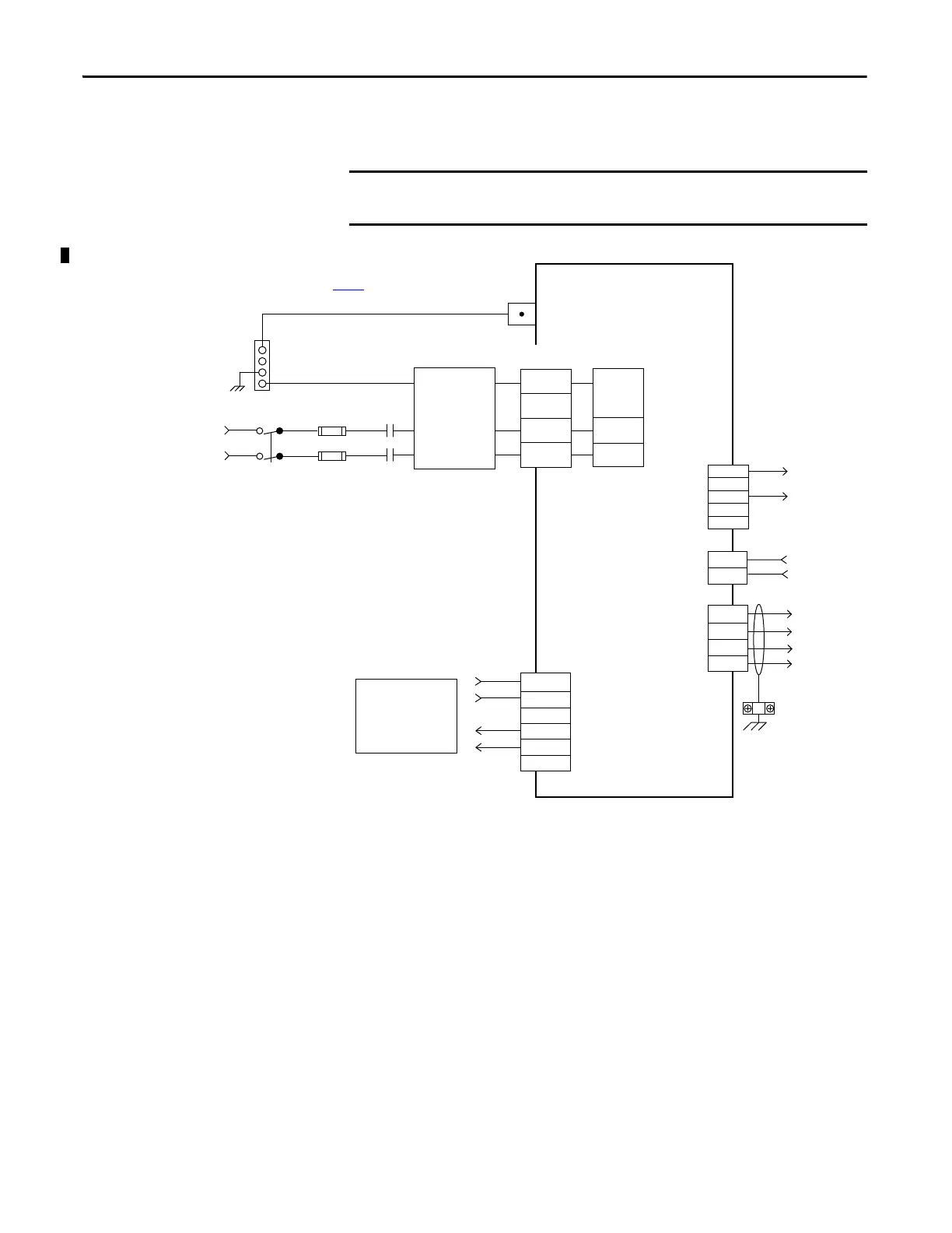
In this example, single-phase 240V AC is applied to 2097-V31PRx and 2097-
V32PRx drives.
Figure 84 - Kinetix 300 Drives (240V single-phase input power)
The 2097-V32PRx models have integrated AC line filters and do not require the
AC line filter shown in this diagram.
L1
L2/N
PE
N
L1
+24V DC
+
+
SH
-
-
EN
ACOM
RDY +
RDY -
29
26
41
42
U
V
W
PE
L2/N
PE
L1
L2
2097-V31PRx
2097-V32PRx
Return
Single-phase AC Input
120/240V rms AC, 50/60 Hz
Notes 1, 2
Ground Stud
Fuse Disconnect
or Circuit Breakers
Input Fusing *
M1 *
Notes 5, 7
Use discrete logic or PLC
to control ENABLE to drive
and monitor RDY signal
back from drive.
Motor Power
(MP) Connector
I/O (IOD)
Connector
2097-V31PRx and 2097-V32PRx
Kinetix 300 Drive
* Indicates User Supplied Component
See table on page 172
for note information.
AC Line Filter
(Optional)
Note 3
Three-phase
Motor Power
Connections
Note 9
Cable Shield
Clamp
Note 8
Shunt Resistor
Connections
User-supplied
+24V DC
Back-up Power
(BP) Connector
Shunt Resistor
and DC Bus
(BC) Connector
Mains
Single-phase
AC Input
(IPD) Connector
Bonded Cabinet
Ground Bus *

 Loading...


