EasyManuals Logo

Allen-Bradley PanelView Plus 7 User Manual

Allen-Bradley PanelView Plus 7
154 pages
To Next Page IconTo Next Page
To Previous Page IconTo Previous Page
Page #33 background imageLoading...
Page #33 background image
Rockwell Automation Publication 2711P-UM007D-EN-P - December 2015 33
Install the PanelView Plus 7 Standard Terminal Chapter 2
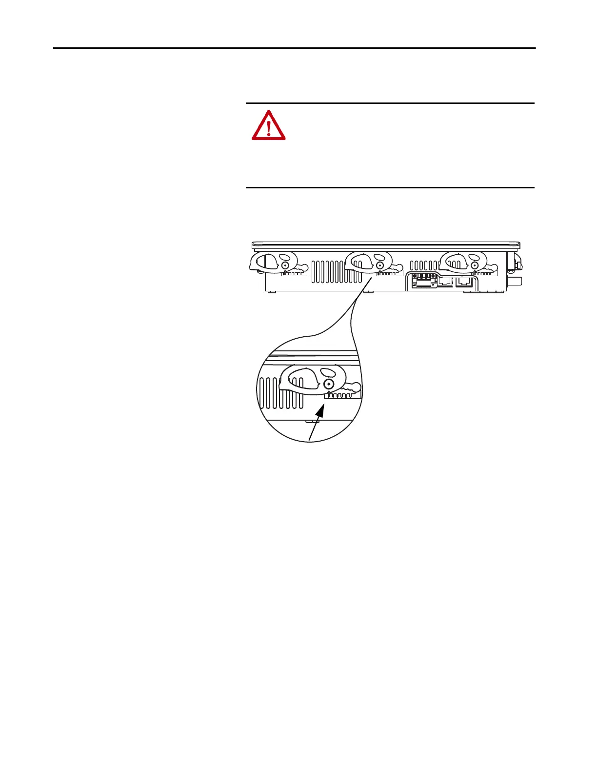
8. To make sure each is in the correct locked position, inspect all mounting
levers.
The notch on the outside of mounting lever shows its locked position.
This view shows that the mounting levers are locked in position 1.
ATTENTION: All mounting levers must be in the correct locked
position and follow the correct lever installation sequence to provide
an adequate gasket seal between the terminal and the panel.
Rockwell Automation assumes no responsibility for water or
chemical damage to the terminal or other equipment within the
enclosure because of improper installation.
6
1
6
66
Series B terminal with dual
Ethernet ports shown.

Table of Contents

Other manuals for Allen-Bradley PanelView Plus 7

Questions and Answers:

Question and Answer IconNeed help?

Do you have a question about the Allen-Bradley PanelView Plus 7 and is the answer not in the manual?

Allen-Bradley PanelView Plus 7 Specifications

General IconGeneral
Operating SystemWindows CE 6.0
Memory512 MB RAM
MountingPanel mount
Display TypeColor TFT LCD
ProcessorARM Cortex-A8
Storage512 MB Flash
Communication PortsEthernet, USB, Serial
Input Voltage24V DC
Operating Temperature0°C to 50°C (32°F to 122°F)
Environmental RatingNEMA 4X
Storage Temperature-20°C to 60°C (-4°F to 140°F)
Relative Humidity5% to 95% non-condensing
CertificationsCE, UL, cUL
Display Sizes4.3", 7", 10", 15", 19"
TouchscreenResistive or Projected Capacitive (depending on model)

Related product manuals