Rockwell Automation Publication 2711P-UM007D-EN-P - December 2015 37
Install the PanelView Plus 7 Standard Terminal Chapter 2
The maximum cable length between the Ethernet ports and a 10/100Base-T
port on an Ethernet hub (without repeaters or fiber) is 100 m (328 ft).
The Ethernet port has two indicators that provide the status of activity.
Device Level Ring Network Topology
A DLR network is a single-fault tolerant ring network that is intended for the
interconnection of automation devices. This topology is also implemented at
the device level. No additional switches are required.
IMPORTANT To help prevent accidental disconnection of the Ethernet cable, follow these
steps:
• To minimize vibration at the connector, and reduce the chance that
personnel working inside the panel can accidentally disconnect the
cable, secure the Ethernet cable.
• To prevent pulling on the cable when the panel door is opened and
closed, do not install the Ethernet cable too tightly. Leave some slack in
the cable.
WARNING: Do not connect or disconnect any communication cable with
power applied to this device or any device on the network. An electric arc
can cause an explosion in hazardous location installations. Make sure that
the power is off or the area is nonhazardous before proceeding.
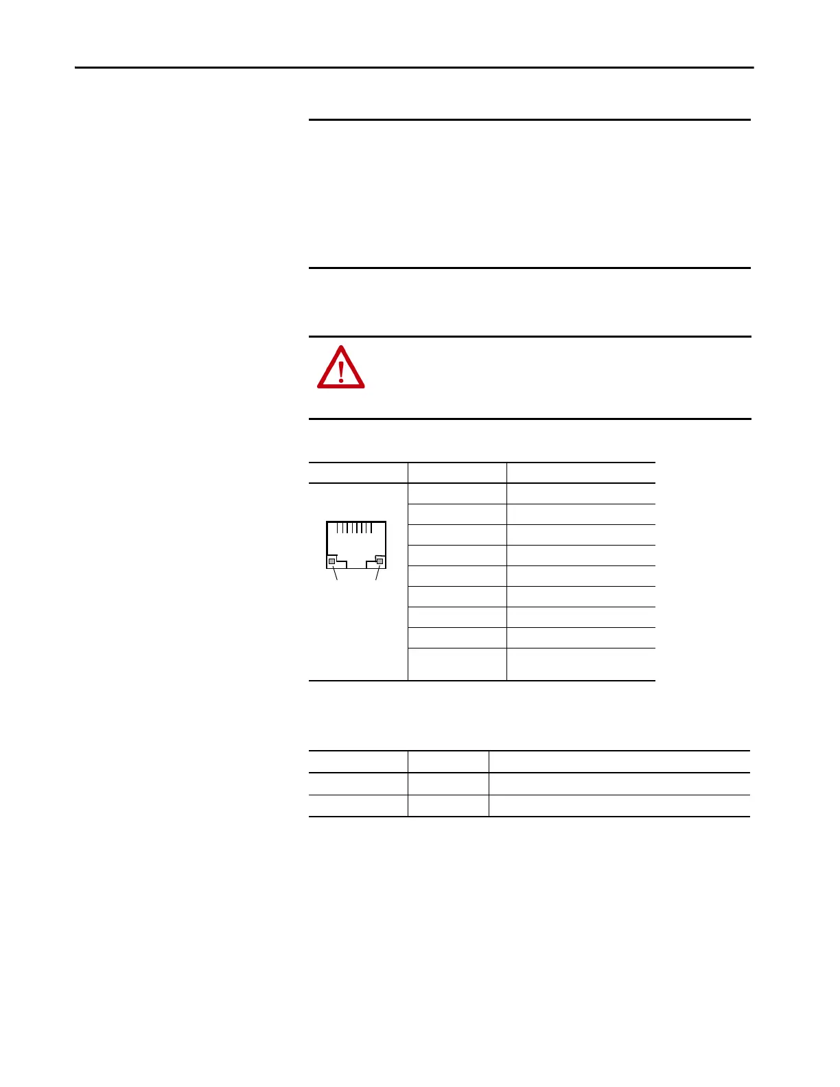
Table 16 - Ethernet Connector Pinout
Connector Pin Pin Name
View of RJ45
Connector
1TD+
2TD-
3RD+
4Unused
5Unused
6RD-
7Unused
8Unused
Shield connection No direct connection
(AC coupled to chassis GND)
Table 17 - Ethernet Status Indicators
Indicator Color Description
Link integrity Green On, when a link is present.
Activity Yellow Blinks when activity is detected on Ethernet link.
TIP A DLR network has supervisor nodes and ring nodes. The PanelView Plus 7
Standard terminal operates only as a ring node on the network.
1
8
Yel low
Status
Indicator
Green
Status
Indicator

 Loading...