3-48 Programming and Parameters
Aux Relay Card Group (continued)
Refer to Appendix C for details on the application of parameters R239
through R254.
R222 [Relay Out3 Level]
R225 [Relay Out4 Level]
R228 [Relay Out5 Level]
R231 [Relay Out6 Level]
R234 [Relay Out7 Level]
R237 [Relay Out8 Level]
Sets the trip point for the digital output relay if the value of [Relay OutX Sel] is 6, 7, 8, 9, 10 or 12.
Values Default: 0.0
Min/Max: 0.0/9999
Display: 0.1
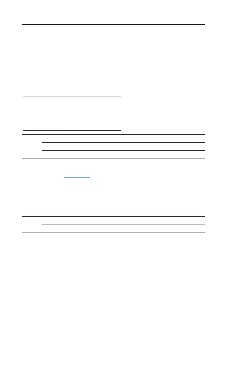
[Relay OutX Select Setting [Relay OutX Level] Min/Max
6
7
8
9
10
12
0/320 Hz
0/180%
0/815 Volts
0/100%
1/180 degs
0/1
R239 [Aux Motor Mode]
Enables operation of the auxiliary motor control modes when in PID mode.
Options 0 “Disabled” (Default)
1 “Enabled”

 Loading...


