Appendix D
Application Notes
The PowerFlex 400 allows damper control logic to be imbedded within
the drive reducing cost associated with external control hardware and
software. A system Run command can be wired directly into one of the
drive inputs. Relay outputs can be used to energize the damper to either
open or close. A damper limit switch can be wired back to the drive
providing indication that the damper is in the proper position and that it
is safe for the drive to run at commanded speed.
Example
• The System Run Command can come from a terminal block, integral
keypad, or communication port. Configure parameter P036 [Start
Source] per application requirements.
• Set one of the available digital inputs, parameter T051
-T054 [Digital
Inx Sel] to option 36 “Damper Input”. The damper end switch or
limit switch should be wired into this input.
• Set one of the available relay outputs, parameter T055
/T060 [Relay
Outx Sel] to option 2 “Motor Running”. This output should be used
to energize the damper to either open or close.
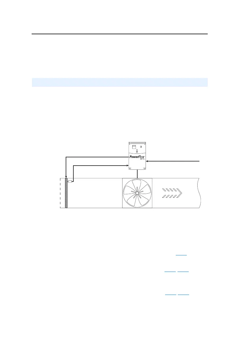
Damper Control Setup
Supply Fan
Air Flow
Damper Limit Switch
Damper Position Command
System Run Command
Outside Air
Damper

 Loading...


