Application Notes D-11
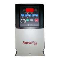
The PowerFlex 400 has a built in Auxiliary Motor Control feature. This
feature allows operation of up to three (3) line-started motors in addition
to the motor controlled directly by the PowerFlex 400 drive. System
output can vary from 0% (auxiliary motors off and drive-controlled
motor at zero speed) to 400% (3 auxiliary motors and drive-controlled
motor at full speed). To enable the Auxiliary Motor Control, parameter
R239
[Aux Motor Mode] must be set to an option 1 “Enabled.” When
enabled, the internal PID controller in the PowerFlex 400 uses a
reference and feedback signal to adjust the speed of the drive controlled
motor such that the feedback signal follows the reference signal. When
demand exceeds the first motors capacity, the PowerFlex 400 Auxiliary
Motor Control automatically starts an auxiliary motor. The speed of the
drive controlled motor is reduced to account for the auxiliary motors
additional output to the system. If demand continues to increase, the
PowerFlex Auxiliary Motor Control starts additional motors using the
same process. When demand decreases, an auxiliary motor is stopped
and the PowerFlex Auxiliary Motor Control increases the speed of the
drive controlled motor to account for lost system output. A Motor
Interlock input identifies motors that are out of service and causes them
to skipped over to the next available motor.
An AutoSwap function also can be used which allows equal wear to be
placed on each motor by periodically swapping the drive controlled and
auxiliary motors. Each motor in the system will over time be connected
to the PowerFlex 400 drive and also directly to the AC line. During an
AutoSwap, the motor directly connected to the PowerFlex 400 drive is
stopped and the contactor is opened. The contactor of the next motor
that will be controlled by the PowerFlex 400 drive is opened if running
across the AC line. A contactor is closed connecting this motor directly
to the PowerFlex 400 drive and is started. An additional motor is line
started if required.
Auxiliary Motor Control Setup

 Loading...


