Programming and Parameters 3-19
Terminal Block Group (continued)
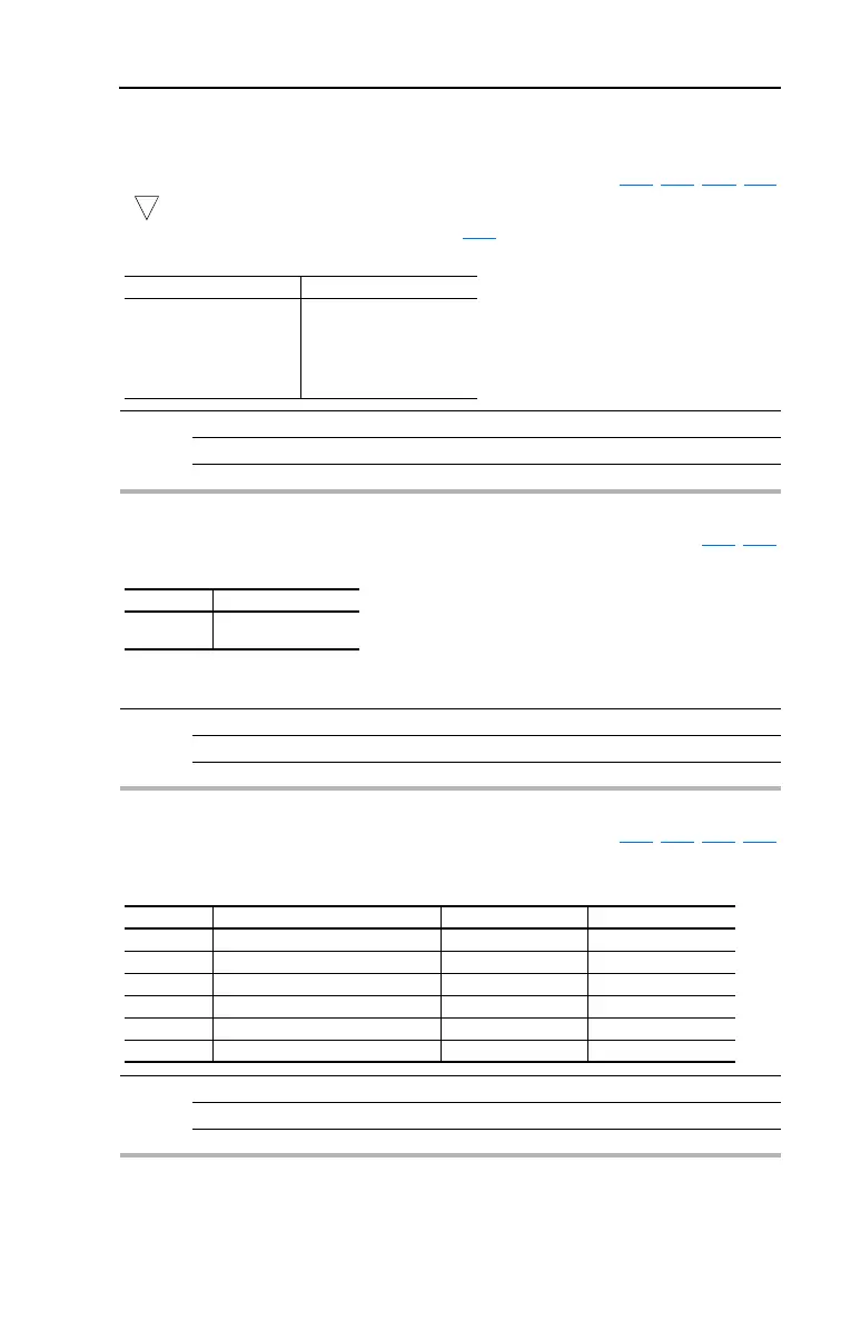
T066 [Opto Out Level] Related Parameter(s): T065, T068, A163, d318
32 bit parameter.
Determines the on/off point for the opto output when T065
[Opto Out Sel] is set to option 6, 7, 8, 9, 10
or 12.
Values Default: 0.0
Min/Max: 0.0/9999
Display: 0.1
32
T065 Setting T066 Min/Max
6
7
8
9
10
12
0/400 Hz
0/180%
0/815 Volts
0/100%
1/180 degs
0/1
T068 [Opto Out Logic] Related Parameter(s): T065, T066
Determines the logic (Normally Open/NO or Normally Closed/NC) of the opto output.
Note: Setting output to NC may cause output to “glitch” on power-up. The off/reset state of all outputs
is open.
Values Default: 0
Min/Max: 0/1
Display: 1
T068 Option Opto Out Logic
0
1
NO (Normally Open)
NC (Normally Closed)
T069 [Analog In 1 Sel] Related Parameter(s): T055, T070, T071, T072
Sets the analog input signal mode (0-20mA, 4-20mA, or 0-10V). This parameter must match DIP
Switch AI1 setting on the control board.
Values Default: 2
Min/Max: 0/6
Display: 1
T069 Option Setting Input Range DIP Switch AI1 Setting
0 Current Mode 0-20 mA 20 mA
1 Current Mode 4-20 mA 20 mA
2 Voltage Mode - Unipolar 0-10V 10V
4 Current Mode (Square Root) 0-20 mA 20 mA
5 Current Mode (Square Root) 4-20 mA 20 mA
6 Voltage Mode - Unipolar (Square Root) 0-10V 10V

 Loading...


