Home
Allen-Bradley
Controller
PowerFlex400
Allen-Bradley PowerFlex400 User Manual
5
of 1
of 1 rating
192 pages
Give review
Manual
Specs
To Next Page
To Next Page
To Previous Page
To Previous Page
Loading...
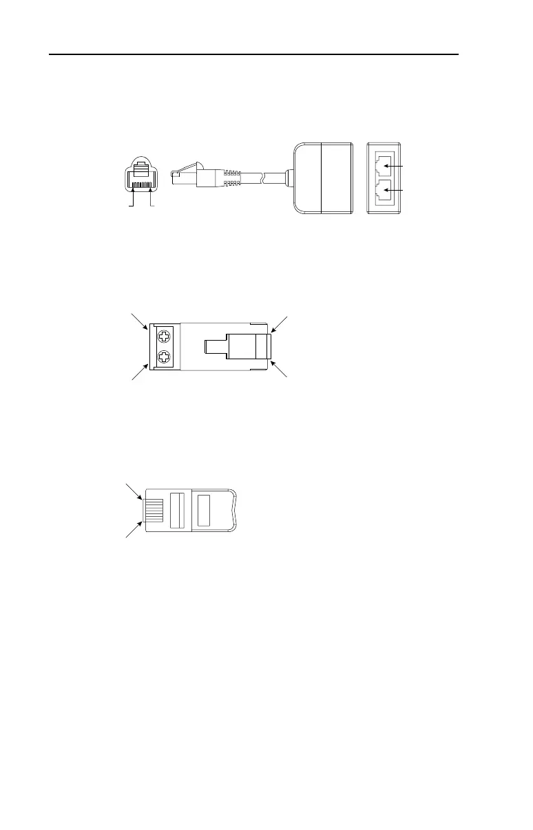
C-2
RJ45 DSI Splitter Cable
DSI Cable Accessories
RJ45 Splitter Cable
– Catalog Number: AK-U0-RJ45-SC1
RJ45 T
wo-P
o
sition T
erminal Block Adapter
–
Catalog Number: AK-U0-RJ4
5-TB2P
RJ45 Adapter with Integrat
ed T
ermination Resistor
–
Catalog Number: AK-U0-RJ4
5-TR1
Slav
e Port
Master P
or
t
PIN
8
PIN 1
M
S
TB2
(PIN 5)
TB1
(PIN 4)
PIN 8
PIN 1
PIN 8
PIN 1
147
149
Table of Contents
Default Chapter
2
Default Chapter
2
Important User Information
2
Important Statement Regarding Differences in Parameter Defaults for
3
Table of Contents
5
Overview
7
Reference Materials
7
Who Should Use this Manual
7
Drive Frame Sizes
8
Manual Conventions
8
General Precautions
9
Catalog Number Explanation
10
Chapter 1 Installation/Wiring
11
Opening the Cover
11
Frame C Mounting Clearances
14
Maximum Surrounding Air Temperature
14
Mounting Considerations
14
Debris Protection
15
Frames D, E and F Mounting Clearances
15
Storage
15
AC Supply Source Considerations
16
Jumper Location
16
Phase to Ground MOV Removal
16
Ungrounded Distribution Systems
16
Input Power Conditioning
17
General Grounding Requirements
18
Ground Fault Monitoring
18
Safety Ground
18
Shield Termination - SHLD
18
Fuses and Circuit Breakers
19
RFI Filter Grounding
19
Recommended Branch Circuit Protective Devices
20
Motor Cable Types Acceptable for 200-600 Volt Installations
21
Power Wiring
21
Shielded/Armored Cable
21
Unshielded
21
Recommended Shielded Wire
22
Maximum Cable Length Recommendations
23
Output Disconnect
23
Reflected Wave Protection
23
Power Terminal Block
24
I/O Wiring Recommendations
25
Motor Start/Stop Precautions
25
Power Terminal Block Specifications
25
Control Wire Types
26
I/O Terminal Block
26
Maximum Control Wire Recommendations
26
Recommended Control and Signal Wire
26
Control Wiring Block Diagram
27
Control I/O Terminal Designations
28
Relay Terminal Designations and DIP Switches
29
User Installed Auxiliary Relay Card
29
User Installed Relay Board Terminal Designations
29
I/O Wiring Examples
30
Typical Multiple Drive Connection Examples
33
Start and Speed Reference Control
34
Accel/Decel Selection
35
Frame D, E, and F RS485 Ports
36
Network Wiring Diagram
36
On Drive Connections
36
RS485 Network Wiring
36
EMC Instructions
37
Connections and Grounding
39
FCC Instructions
39
Before Applying Power to the Drive
43
Prepare for Drive Start-Up
43
Applying Power to the Drive
44
Start, Stop, Direction and Speed Control
44
Integral Keypad
45
Operator Keys
45
LCD Display
46
LED Status Indicators
46
Viewing and Editing Parameters
47
Hand-Off-Auto Mode
48
Keypad Hand-Off-Auto Functions
48
Local/Remote Mode
49
Auto/Manual Mode
50
No Function Mode
51
Chapter 2 Start up
53
Chapter 3 Programming and Parameters
53
About Parameters
53
Parameter Organization
54
Basic Display Group
56
B001 [Output Freq]
56
B002 [Commanded Freq]
56
B003 [Output Current]
56
B006 [Drive Status]
57
B007 [Fault 1 Code]
57
B008 [Process Display]
57
B010 [Output Power]
57
B011 [Elapsed Mwh]
58
B012 [Elapsed Run Time]
58
B013 [Torque Current]
58
B014 [Drive Temp]
58
P031 [Motor NP Volts]
59
P032 [Motor NP Hertz]
59
P033 [Motor OL Current]
59
P034 [Minimum Freq]
59
Basic Program Group
59
P036 [Start Source]
60
P037 [Stop Mode]
61
Hardware Enable Circuitry
61
P038 [Speed Reference]
62
P039 [Accel Time 1]
62
P040 [Decel Time 1]
63
P041 [Reset to Defalts]
63
P042 [Auto Mode]
63
P043 [Motor OL Ret]
63
Terminal Block Group
64
T051/T052/T053/T054
64
T055 [Relay Out1 Sel]
66
T056 [Relay Out1 Level]
67
T058 [Relay 1 on Time]
67
T059 [Relay 1 off Time]
67
T060 [Relay Out2 Sel]
68
T061 [Relay Out2 Level]
69
T063 [Relay 2 on Time]
69
T064 [Relay 2 off Time]
69
T065 [Opto out Sel]
70
T066 [Opto out Level]
71
T068 [Opto out Logic]
71
T069 [Analog in 1 Sel]
71
T070 [Analog in 1 Lo]
72
T071 [Analog in 1 Hi]
72
T072 [Analog in 1 Loss]
73
T073 [Analog in 2 Sel]
73
T074 [Analog in 2 Lo]
74
T075 [Analog in 2 Hi]
74
T076 [Analog in 2 Loss]
74
T077 [Sleep-Wake Sel]
75
T078 [Sleep Level]
75
T079 [Sleep Time]
75
T080 [Wake Level]
75
T082 [Analog Out1 Sel]
76
T083 [Analog Out1 High]
76
T084 [Anlg Out1 Setpt]
77
T085 [Analog Out2 Sel]
77
T086 [Analog Out2 High]
78
T087 [Anlg Out2 Setpt]
78
T088 [Anlg Loss Delay]
78
Communications Group
79
C101 [Language]
79
C102 [Comm Format]
79
C103 [Comm Data Rate]
79
C104 [Comm Node Addr]
80
C105 [Comm Loss Action]
80
C106 [Comm Loss Time]
80
C107 [Comm Write Mode]
80
C108 [Start Source 2]
81
C109 [Speed Ref 2]
82
Advanced Program Group
83
A141 [Purge Frequency]
83
A142 [Internal Freq]
83
A143/A144/A145/A146
83
A147 [Accel Time 2]
84
A148 [Decel Time 2]
84
A149 [S Curve %]
85
A150 [PID Trim Hi]
85
A151 [PID Trim Lo]
85
A152 [PID Ref Sel]
86
A153 [PID Feedback Sel]
86
A154 [PID Prop Gain]
86
A155 [PID Integ Time]
86
A156 [PID Diff Rate]
87
A157 [PID Setpoint]
87
A158 [PID Deadband]
87
A159 [PID Preload]
87
A163 [Auto Rstrt Tries]
88
A164 [Auto Rstrt Delay]
88
A165 [Start at Powerup]
88
A166 [Reverse Disable]
89
A167 [Flying Start En]
89
A168 [PWM Frequency]
89
A169 [PWM Mode]
89
A170 [Boost Select]
90
A171 [Start Boost]
91
A172 [Break Voltage]
91
A173 [Break Frequency]
91
A174 [Maximum Voltage]
92
A175 [Slip Hertz @ FLA]
92
A176 [DC Brake Time]
92
A177 [DC Brake Level]
92
A178 [DC Brk Time@Strt]
93
A179 [Current Limit 1]
93
A180 [Current Limit 2]
93
A181 [Motor OL Select]
93
A182 [Drive OL Mode]
94
A183 [SW Current Trip]
94
A184 [Load Loss Level]
94
A185 [Load Loss Time]
94
A187 [Bus Reg Mode]
95
A188 [Skip Frequency 1]
95
A189 [Skip Freq Band 1]
95
A190 [Skip Frequency 2]
95
A191 [Skip Freq Band 2]
96
A192 [Skip Frequency 3]
96
A193 [Skip Freq Band 3]
96
A194 [Compensation]
97
A195 [Reset Meters]
97
A196 [Testpoint Sel]
97
A197 [Fault Clear]
97
A198 [Program Lock]
98
A199 [Motor NP Poles]
98
A200 [Motor NP FLA]
98
R221/R224/R227/R230/R233/R236
99
Aux Relay Card Group
99
R222/R225/R228/R231/R234/R237
100
R239 [Aux Motor Mode]
100
R240 [Aux Motor Qty]
101
R250 [Aux Start Delay]
102
R251 [Aux Stop Delay]
102
R252 [Aux Prog Delay]
102
R253 [Aux Autoswap Tme]
102
R254 [Aux Autoswap Lvl]
103
Advance Display Group
104
D301 [Control Source]
104
D302 [Contrl in Status]
104
D303 [Comm Status]
105
D304 [PID Setpnt Displ]
105
D305 [Analog in 1]
105
D306 [Analog in 2]
105
D308 [Fault 2 Code]
106
D309 [Fault 3 Code]
106
D310 [Fault 1 Time-Hr]
106
D311 [Fault 1 Time-Min]
106
D313 [Fault 2 Time-Min]
107
D314 [Fault 3 Time-Hr]
107
D315 [Fault 3 Time-Min]
107
D316 [Elapsed Time-Hr]
107
D319 [Testpoint Data]
108
D320 [Control SW Ver]
108
D322 [Output Speed]
108
D323 [Output RPM]
108
D326 [Fault Bus Volts]
109
D327 [Status @ Fault]
109
Parameter Cross-Reference
110
Chapter 4 Troubleshooting
113
Drive Status
113
Faults
113
Fault Indication
114
Manually Clearing Faults
114
Automatically Clearing Faults
114
Auto Restart (Reset/Run)
114
Fault Descriptions
115
Common Symptoms and Corrective Actions
117
Motor Does Not Start
117
Drive Does Not Start from Start/Run Inputs Wired to the Terminal Block
118
Drive Does Not Start from Integral Keypad
118
Drive Does Not Respond to Changes in Speed Command
119
Motor And/Or Drive will Not Accelerate to Commanded Speed
119
Motor Operation Is Unstable
120
Drive will Not Reverse Motor Direction
120
Drive Does Not Power up
120
Supplemental Drive Information
121
Drive, Fuse & Circuit Breaker Ratings
121
Fusing
121
Circuit Breakers
121
Specifications
122
Drive Ratings
122
Powerflex 400 Watts Loss (Rated Load, Speed & PWM)
126
Input Power Connections
127
Frame C, D, and E Connections
127
Frame F Connections
127
Appendix A Supplemental Drive Information
129
Appendix B Accessories and Dimensions
129
Product Selection
129
Catalog Number Description
129
Powerflex 400 Drives
129
Powerflex 400 Flange Mount Drives
130
Bulletin 1321-3R Series Line Reactors – 200-240V, 60 Hz, Three-Phase
130
Bulletin 1321-3R Series Line Reactors – 380-480V, 60 Hz, Three-Phase
131
Bulletin 1321 - DC Series Bus Inductors - 380-480V, 60 Hz, Three-Phase
132
EMC Line Filters
132
Communication Option Kits and Accessories
133
Human Interface Module (HIM) Option Kits and Accessories
134
Frame C IP30/NEMA 1/UL Type 1 Kit
134
Field Installed Option
134
Product Dimensions
135
Powerflex 400 Frames and Weights
135
Powerflex 400 Frame C Flange Mount Drive
140
Bulletin 1321-3R Series Line Reactors
141
Bulletin 1321-DC Series Bus Inductors
142
EMC Line Filters – Dimensions Are in Millimeters and (Inches)
143
Remote (Panel Mount) Small HIM
145
NEMA Type 1 Bezel – Dimensions Are in Millimeters and (Inches)
146
RJ45 DSI Splitter Cable
147
Connectivity Guidelines
147
DSI Cable Accessories
148
RJ45 Splitter Cable
148
RJ45 Two-Position Terminal Block Adapter
148
RJ45 Adapter with Integrated Termination Resistor
148
Connecting One Temporary Peripheral
149
Connecting One Temporary Peripheral and One Permanent Peripheral
149
Connecting Two Permanent Peripherals
150
Connecting an RS-485 Network
150
Application Notes
151
Accessories and Dimensions
129
Appendix C RJ45 DSI Splitter Cable
151
Appendix D Application Notes
151
Damper Control Setup
151
PID Setup
152
PID Control Loop
152
Exclusive Control
153
Trim Control
154
PID Reference and Feedback
155
Analog PID Reference Signals
156
Scale Function
156
Invert Function
156
PID Deadband
157
PID Preload
157
PID Limits
157
PID Gains
158
Guidelines for Adjusting the PID Gains
159
Unstable
160
Slow Response – over Damped
160
Oscillation – under Damped
160
Good Response – Critically Damped
160
Auxiliary Motor Control Setup
161
One External Motor Without Autoswap
162
One External Motor with Autoswap
163
Modbus RTU Protocol
165
Appendix E Modbus RTU Protocol
165
Network Wiring
165
Parameter Configuration
166
Supported Modbus Function Codes
166
Writing (06) Logic Command Data
167
Writing (06) Reference
167
Reading (03) Logic Status Data
168
Reading (03) Feedback
168
Reading (03) Drive Error Codes
169
Reading (03) and Writing (06) Drive Parameters
169
Additional Information
169
Metasys N2 Virtual Objects
171
Understanding Metasys N2
171
Network Points
171
Metasys N2 Data Types
172
Description of the Regions of a Virtual Object
172
Internal Structure of Metasys N2 Analog Input (AI)
172
Internal Structure of Metasys N2 Binary Input (BI)
172
Network Points
173
Binary Inputs
173
Analog Inputs
173
Binary Outputs
174
Analog Outputs
174
Using Percent (%) for the Reference
175
Internal Integer
175
Using Metasys Configurable Objects to Access Parameters
176
Reading Parameter Values
176
Configurable Input Point Operation Objects Inputs
176
Configurable Objects: Inputs
176
Writing Parameter Values
177
Configurable Objects: Outputs
177
Appendix F Metasys N2
179
Appendix G P1 - Floor Level Network (FLN)
179
Understanding P1-FLN
179
Network Points
179
Point Database for Application 2735
181
Using Percent (%) for the Reference
184
Using P1 Configurable Points to Access
185
Configurable Input Point Operation
185
Configurable Output Point Operation
186
Parameters
186
Index
187
P1 - Floor Level Network (FLN)
179
5
Based on 1 rating
Ask a question
Give review
Questions and Answers:
Need help?
Do you have a question about the Allen-Bradley PowerFlex400 and is the answer not in the manual?
Ask a question
Allen-Bradley PowerFlex400 Specifications
General
Brand
Allen-Bradley
Model
PowerFlex400
Category
Controller
Language
English
Related product manuals
Allen-Bradley PowerFlex40
160 pages
Allen-Bradley PowerFlex 4
108 pages
Allen-Bradley PowerFlex 4M
118 pages
Allen-Bradley PowerFlex 40
218 pages
Allen-Bradley PowerFlex 70
132 pages
Allen-Bradley PowerFlex 525
244 pages
Allen-Bradley PowerFlex 755
354 pages
Allen-Bradley powerflex 700
198 pages
Allen-Bradley PowerFlex 400
218 pages
Allen-Bradley PowerFlex 527
354 pages
Allen-Bradley PowerFlex 523
244 pages
Allen-Bradley PowerFlex 755TR
192 pages