1-6 Installation/Wiring
Ungrounded Distribution Systems
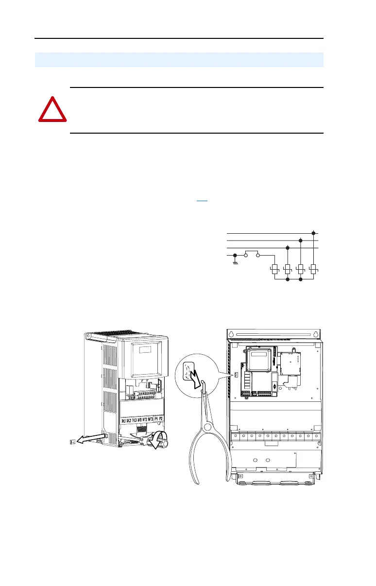
Disconnecting MOVs (Drive Frames C, E and F only.)
To prevent drive damage, the MOVs connected to ground shall be
disconnected if the drive is installed on an ungrounded distribution
system where the line-to-ground voltages on any phase could exceed
125% of the nominal line-to-line voltage. To disconnect these devices,
remove the jumper shown in Figure 1.4
.
Figure 1.3 Phase to Ground MOV Removal
Figure 1.4 Jumper Location
Note: Frame D drives do not contain a MOV to ground connection and
are suitable for operation in both grounded and ungrounded distribution
systems without modification.
AC Supply Source Considerations
!
ATTENTION: PowerFlex 400 drives contain protective MOVs that
are referenced to ground. These devices must be disconnected if the
drive is installed on an ungrounded or resistive grounded distribution
system.
R/L1
S/L2
T/L3
123
4
Three-Phase
AC Input
Jumper
Important:
Tighten screw after
jumper removal.
Frame C
Frame E & F

 Loading...


