Installation/Wiring 1-23
Typical Multiple Drive Connection Examples
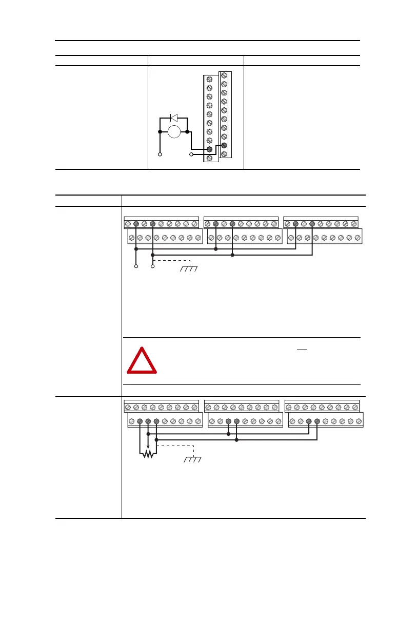
Opto Output
• When using Opto Output with
an inductive load such as a
relay, install a recovery diode
parallel to the relay as shown
to prevent damage to the
output.
• Opto Output is rated 30V DC,
50 mA (non-inductive).
Parameters
T065 [Opto Out Sel] = 0 through 15
T066 [Opto Out Level]
T068 [Opto Out Logic]
Input/Output Connection Example Required Settings
Common+24V
CR
09
19
Input/Output Connection Example
Multiple Digital
Input Connections
Customer Inputs can
be wired per
External Supply
(SRC).
When connecting a single input such as Run, Stop, Reverse or Preset Speeds to
multiple drives, it is important to connect I/O Terminal 04 common together for all
drives. If they are to be tied into another common (such as earth ground or
separate apparatus ground) only one point of the daisy chain of I/O Terminal 04
should be connected.
Multiple Analog
Connections
When connecting a single potentiometer to multiple drives it is important to
connect I/O Terminal 14 common together for all drives. I/O Terminal 14 common
and I/O Terminal 13 (potentiometer wiper) should be daisy-chained to each drive.
All drives must be powered up for the analog signal to be read correctly.
Customer Inputs Optional Ground Connection
04020402 0402
!
ATTENTION: I/O Common terminals should not be tied together
when using SNK (Internal Supply) mode. In SNK mode, if power is
removed from one drive, inadvertent operation of other drives that
share the same I/O Common connection may occur.
Remote Potentiometer Optional Ground Connection
12 13 1413 14 13 14

 Loading...


