Installation/Wiring 1-19
Table 1.H Relay Terminal Designations and DIP Switches
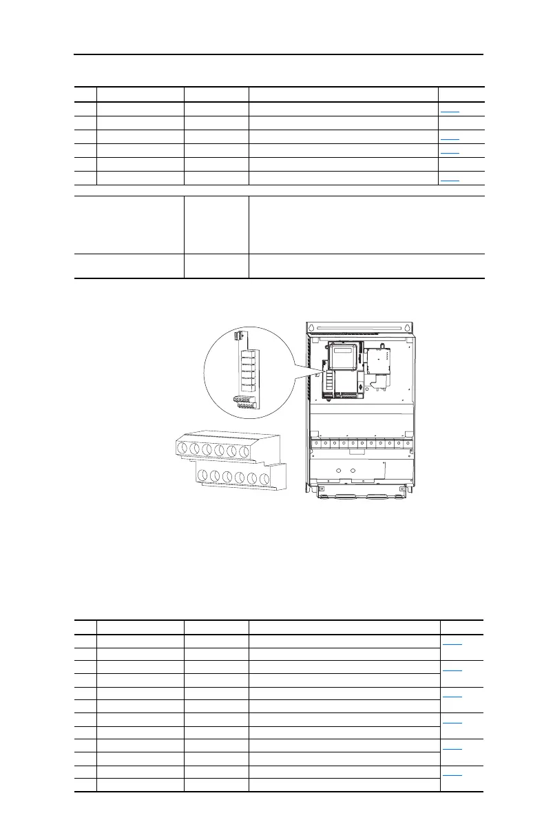
Figure 1.8 User Installed Auxiliary Relay Card (Frames D, E, & F Only)
Important: If using auxiliary motor control, ensure that wiring and parameter
configuration are correct before wiring contactor outputs. All relays
on the Auxiliary Relay Card will energize on power-up by default.
Failure to verify proper wiring and parameter configuration can result
in improper motor operation or drive damage. Refer to Appendix D
for more details.
Table 1.I User Installed Relay Board Terminal Designations
No. Signal Default Description Param.
R1 #1 Relay N.O. Ready/Fault Normally open contact for No. 1 output relay. T055
R2 #1 Relay Common – Common for output relay.
R3 #1 Relay N.C. Ready/Fault Normally closed contact for No. 1 output relay. T055
R4 #2 Relay N.O. Motor Running Normally open contact for No. 2 output relay. T060
R5 #2 Relay Common – Common for output relay.
R6 #2 Relay N.C. Motor Running Normally closed contact for No. 2 output relay. T060
Selection DIP Switches:
Analog Input (AI1 & AI2)
Analog Output (AO1 & AO2)
0-10V Sets analog output to either voltage or current.
Settings must match: AI1 & T069 [Analog In 1 Sel]
AI2 & T073 [Analog In 2 Sel]
AO1 & T082 [Analog Out1 Sel]
AO2 & T085 [Analog Out2 Sel]
Sink/Source DIP Switch Source (SRC) Inputs can be wired as Sink (SNK) or Source (SRC) via DIP
Switch setting.
3A
3B
4A
4B
5A
5B
6A
6B
7A
7B
8A
8B
No. Signal Default Description Param.
3A #3 Relay N.O. Ready/Fault Normally open contact for Number 3 Output Relay R221
3B #3 Relay Common – Common for Number 3 Output Relay
4A #4 Relay N.O. Ready/Fault Normally open contact for Number 4 Output Relay R224
4B #4 Relay Common – Common for Number 4 Output Relay
5A #5 Relay N.O. Ready/Fault Normally open contact for Number 5 Output Relay R227
5B #5 Relay Common – Common for Number 5 Output Relay
6A #6 Relay N.O. Ready/Fault Normally open contact for Number 6 Output Relay R230
6B #6 Relay Common – Common for Number 6 Output Relay
7A #7 Relay N.O. Ready/Fault Normally open contact for Number 7 Output Relay R233
7B #7 Relay Common – Common for Number 7 Output Relay
8A #8 Relay N.O. Ready/Fault Normally open contact for Number 8 Output Relay R236
8B #8 Relay Common – Common for Number 8 Output Relay

 Loading...


