1-4 Installation/Wiring
• Mount the drive upright on a flat, vertical and level surface.
• Protect the cooling fan by avoiding dust or metallic particles.
• Do not expose to a corrosive atmosphere.
• Protect from moisture and direct sunlight.
Maximum Surrounding Air Temperature
Minimum Mounting Clearances
Refer to Appendix B for mounting dimensions.
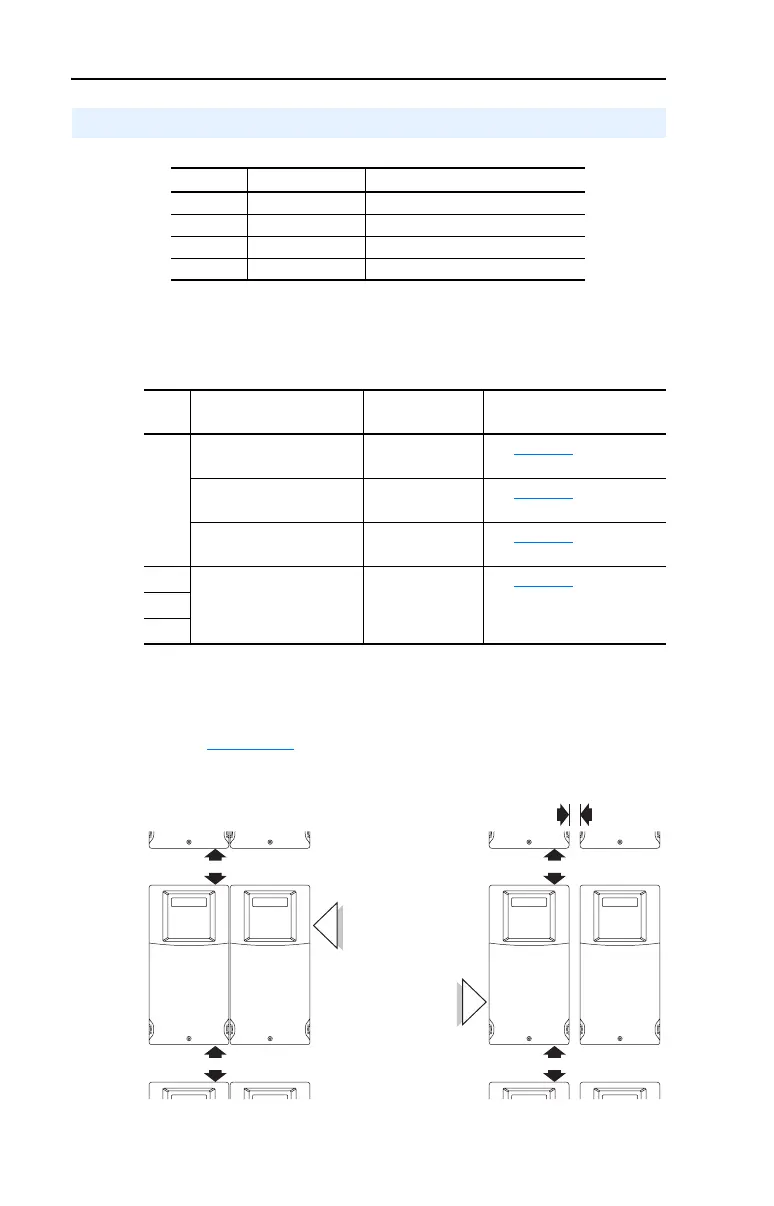
Figure 1.1 Frame C Mounting Clearances
Mounting Considerations
Frame Screw Size Screw Torque
C M5 (#10-24) 2.45-2.94 N-m (22-26 lb.-in.)
D M8 (5/16 in.) 6.0-7.4 N-m (53.2-65.0 lb.-in.)
E M8 (5/16 in.) 8.8-10.8 N-m (78.0-95.3 lb.-in.)
F M10 (3/8 in.) 19.6-23.5 N-m (173.6-208.3 lb.-in.)
Frame Enclosure Rating Temperature
Range
Minimum Mounting
Clearances
C IP 20/UL Open-Type -10° to 45°C
(14° to 113°F)
See Figure 1.1
,
Mounting Option A
IP 30/NEMA 1/UL Type 1
(1)
(1)
Frame C drives require installation of the PowerFlex 400 IP 30/NEMA 1/UL Type 1
option kit to achieve this rating.
-10° to 45°C
(14° to 113°F)
See Figure 1.1
,
Mounting Option B
IP 20/UL Open-Type -10° to 50°C
(14° to 122°F)
See Figure 1.1
,
Mounting Option B
D IP 30/NEMA 1/UL Type 1 -10° to 45°C
(14° to 113°F)
See Figure 1.2
E
F
120 mm
(4.7 in.)
120 mm
(4.7 in.)
120 mm
(4.7 in.)
120 mm
(4.7 in.)
25 mm
(1.0 in.)
Mounting Option B
Mounting Option A
No clearance required
between drives.

 Loading...


