Installation/Wiring 1-15
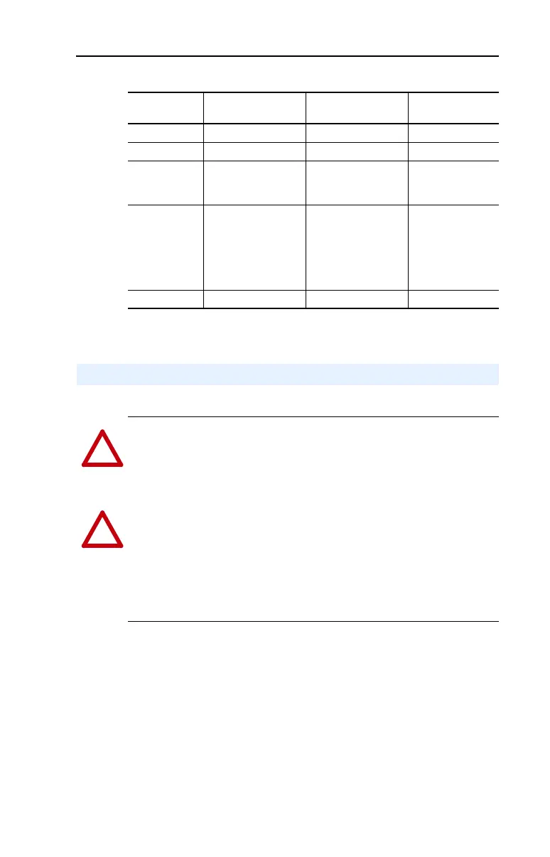
Table 1.D Power Terminal Block Specifications
Motor Start/Stop Precautions
Frame Maximum Wire Size
(1)
(1)
Maximum/minimum sizes that the terminal block will accept - these are not
recommendations. If national or local codes require sizes outside this range, lugs may
be used.
Minimum Wire Size
(1)
Recommended
Torque
C 8.4 mm
2
(8 AWG) 1.3 mm
2
(16 AWG) 2.9 N-m (26 lb.-in.)
D 33.6 mm
2
(2 AWG) 8.4 mm
2
(8 AWG) 5.1 N-m (45 lb.-in.)
E 480V
37-45 kW
(50-60 HP)
33.6 mm
2
(2 AWG) 3.5 mm
2
(12 AWG) 5.6 N-m (49.5 lb.-in.)
E 240V
30-37 kW
(40-50 HP)
480V
55-75 kW
(75-100 HP)
107.2 mm
2
(4/0 AWG) 53.5 mm
2
(1/0 AWG) 19.5 N-m (173 lb.-in.)
F 152.5 mm
2
(300 MCM) 85.0 mm
2
(3/0 AWG) 19.5 N-m (173 lb.-in.)
I/O Wiring Recommendations
!
ATTENTION: A contactor or other device that routinely disconnects
and reapplies the AC line to the drive to start and stop the motor can
cause drive hardware damage. The drive is designed to use control input
signals that will start and stop the motor. If used, the input device must
not exceed one operation per minute or drive damage can occur.
!
ATTENTION: The drive start/stop control circuitry includes
solid-state components. If hazards due to accidental contact with
moving machinery or unintentional flow of liquid, gas or solids exist,
an additional hardwired stop circuit may be required to remove the AC
line to the drive. When the AC line is removed, there will be a loss of
any inherent regenerative braking effect that might be present - the
motor will coast to a stop. An auxiliary braking method may be
required.

 Loading...


