1-14 Installation/Wiring
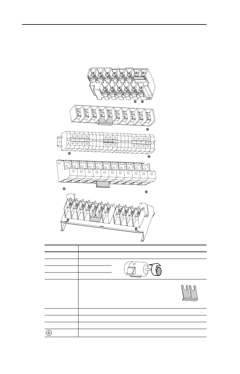
Power Terminal Block
Frame C, D, and F drives utilize a finger guard over the power wiring
terminals. Replace the finger guard when wiring is complete.
Figure 1.6 Power Terminal Blocks
Terminal
(1)
Description
R/L1, S/L2, T/L3 3-Phase Input
U/T1 To Motor U/T1
=
Switch any two motor
leads to change
forward direction.
V/T2 To Motor V/T2
W/T3 To Motor W/T3
P2, P1
DC Bus Inductor Connection
Drives are shipped with a jumper between Terminals
P2 and P1. Remove this jumper only when a DC Bus
Inductor will be connected. Drive will not power up
without a jumper or inductor connected.
DC–, DC+ DC Bus Connection (Frame C Drives)
P2, DC– DC Bus Connection (Frame D, E, and F Drives)
BR+, BR– Not Used
Safety Ground - PE
(1)
Important: Terminal screws may become loose during shipment. Ensure that all
terminal screws are tightened to the recommended torque before applying power to
the drive.
Frame C
Frame D
Frame E:
480V
37-45kW
(50-60HP)
R/L1 S/L2 T/L3
U/T1 V/T2
W/T3
P2 P1
BR–BR+DC+DC–
R/L1
R/L1
S/L2
S/L2
T/L3
T/L3
P1
P1
P2
P2
DC–
DC–
U/T1
U/T1
V/T2
V/T2
W/T3
W/T3
Frame E:
240V 480V
30-37kW 55-75kW
(40-50HP) (75-100HP)
Frame F
R/L1
S/L2
T/L3
P1
P2
DC–
U/T1
V/T2
W/T3
R/L1
S/L2
T/L3
P1
P2
DC–
U/T1
V/T2
W/T3

 Loading...


