Application Notes D-13
Example 2
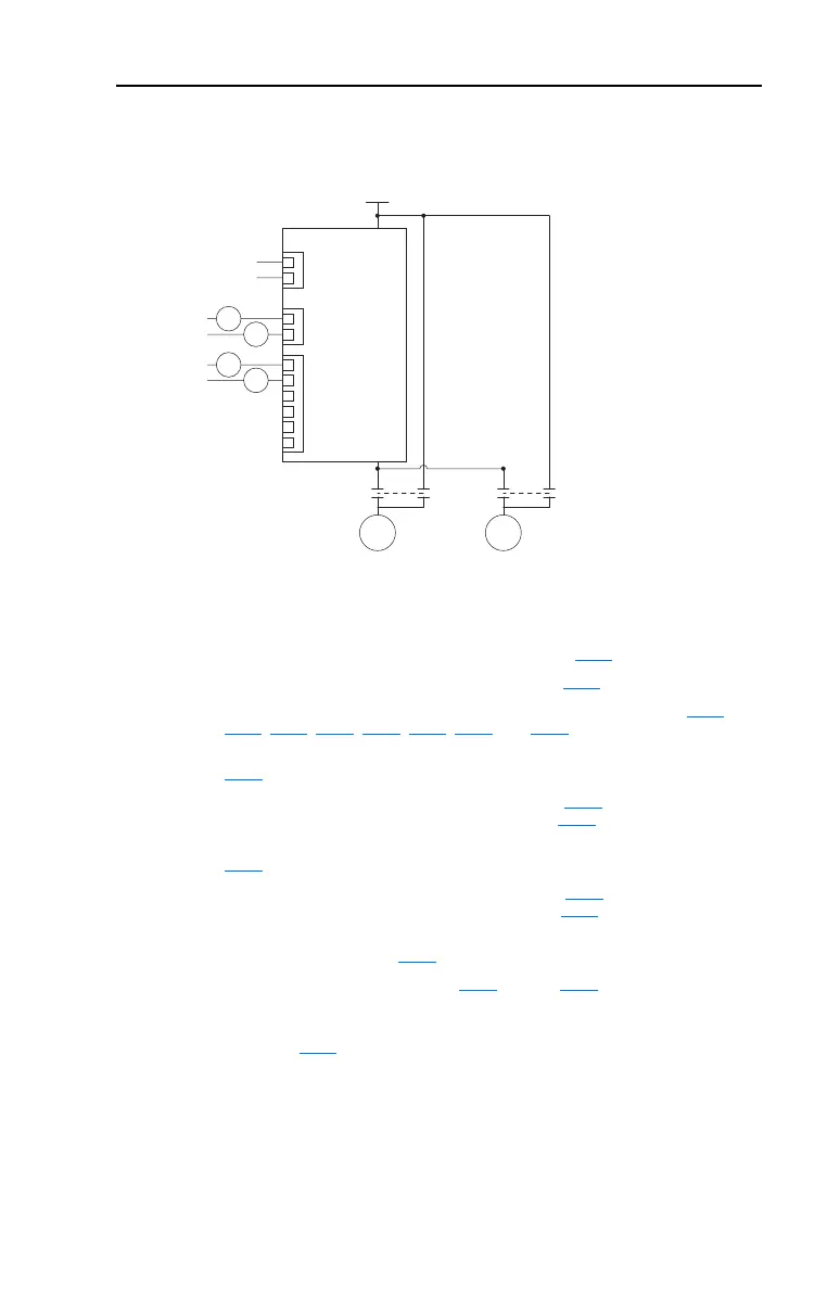
One External Motor with AutoSwap
(1) Mechanically interlocked contactors are recommended to ensure that the
drive contactor and the line contactor do not close at the same time. If the
drive and line contactor close at the same time, drive damage may result.
• Auxiliary Motor Control is enabled via Parameter R239
[Aux Motor Mode].
• Number of auxiliary motors is set via Parameter R240
[Aux Motor Qty].
• Relays are configured for Auxiliary Motor Control via parameters T055
,
T060, R222, R225, R228, R231, R234, and R237.
• The frequency of Motor #1 that Motor #2 turns on at is set via Parameter
R241
[Aux 1 Start Freq].
• The time that Motor #1 is above the value set by R241
[Aux 1 Start Freq]
before turning on Motor #2 is set via Parameter R250 [Aux Start Delay].
• The frequency of Motor #1 that Motor #2 turns off at is set via Parameter
R242
[Aux 1 Stop Freq].
• The time that Motor #1 is below the value set by R242
[Aux 1 Stop Freq]
before turning off Motor #2 is set via Parameter R251 [Aux Stop Delay].
• The running time between the PowerFlex 400 switching control from Motor
#1 to Motor #2 is set via R253
[Aux AutoSwap Time].
• PID setup is done via Parameters A150
through A159. See Appendix D for
additional information.
• The maximum PID output level that an AutoSwap can occur is set via
Parameter R254
[Aux AutoSwap Lvl]. AutoSwap will be delayed until the
PID output drops below this parameter setting.
Important: If using auxiliary motor control, ensure that wiring and parameter
configuration are correct before wiring contactor outputs. All relays
on the Auxiliary Relay Card will energize on power-up by default.
Failure to verify proper wiring and parameter configuration can result
in improper motor operation or drive damage.
PID
Reference
Feedback
Drive Relays
Auxiliary Relay Card
M1D M1L M2D M2L
PowerFlex 400
Three-Phase Power
M1D
M1L
M2D
M2L
M1 M2
(1) (1)

 Loading...


