162 Rockwell Automation Publication 1560F-UM001A-EN-P - June 2019
Chapter 9 Troubleshooting
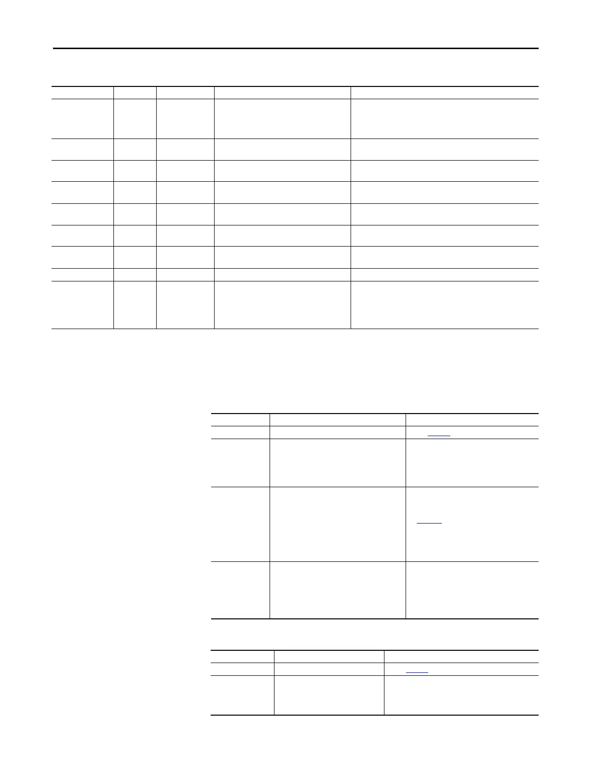
Table 59 - Motor Will Not Start—No Output Voltage to the Motor
Table 60 - Motor Rotates but Does Not Accelerate to Full Speed
Locked Rotor 70 In All Modes • Motor has stalled; rotor is not turning
• Check motor and load for binding or jammed conditions
• Parameters are not adequately configured for the application.
Review and adjust.
• Disable the fault/alarm feature.
Start 71 Starting
• A start event (command) has occurred. This is
not a fault.
•NA
Stop Option 73 Stop Option
• A stop option event (command) has occurred.
This is not a fault.
•NA
Coast 74 Coast
• A coast-to-stop event (command) has
occurred. This is not a fault.
•NA
Clear Fault 75 Faulted
• A clear fault event (command) has occurred.
This does not generate a fault.
•NA
Fault 76 Faulted
• A fault event (command) has occurred. This is
not a fault.
•NA
Param Change 77 Stopped
• A change to one of the controller parameters
has occurred. This is not a fault.
•NA
Reserved 78…99 NA • NA • NA
System Faults 100…199 In All Modes
• There is an issue with the control module
wiring
• The control module is defective
• Review the control module wiring. Ensure the ground terminal is
secure and connected to the system’s earth ground. Ensure an RC
snubber/suppressor is connected to all inductive loads in the
control circuit. See input wiring.
• Replace the control module.
(1) The Real, Reactive, and Apparent Power faults/alarms are best suited to provide indication of an abnormal running operation of the motor or system which another parameter (for example,
Underload, Overload, Jam, Stall, etc.) does not provide. To understand what is an abnormal running operation, you need to determine a "normal" or "typical" value, usually established during system
startup.
(2) "X" indicates a port number in which the expansion module resides in the SMC-50 control module .
(3) If controller based motor overload is disabled, external motor overload protection should be used.
Table 58 - Fault Display Explanation (Continued)
Display Fault Code Fault Enabled Possible Causes Possible Solutions
Display Possible Cause Possible Solutions
Fault displayed • See fault description • See Table 58
addressing fault conditions
HIM display is blank
•Failed HIM
• Control voltage is absent
• Failed control module
• HIM connection is loose
• Check control wiring and correct if necessary
• Check HIM connection
• Cycle control power
• Replace HIM only
• Replace control module only
Stopped
0.0 Amps
•Pilot devices
• SMC Enable input is open at terminal 9
• Configured or wired input terminals are not
wired correctly
• Start-Stop control has not been enabled for
the human interface module
•Control voltage
• Failed control module
• Check wiring; follow the instructions on
page 137
to enable control capability.
•Check control voltage
• Replace control module
Starting
•One or more power phases are missing
• Isolation contactor (if used) is not picking up
• Check power system
• Check that the controller Aux. relay output
controlling the Isolation Contactor is
configured to "Normal".
• Check the Isolation Contactor for proper
operation
Display Possible Cause Possible Solutions
Fault displayed • See fault description • See Table 58
addressing fault conditions
Starting
• Mechanical problems
Inadequate Current Limit setting
• Failed control module
• Check for binding or external loading and correct
• Check motor
• Adjust the Current Limit Level to a higher setting
• Replace control module

 Loading...


