232 Rockwell Automation Publication 1560F-UM001A-EN-P - June 2019
Appendix A Parameter Information
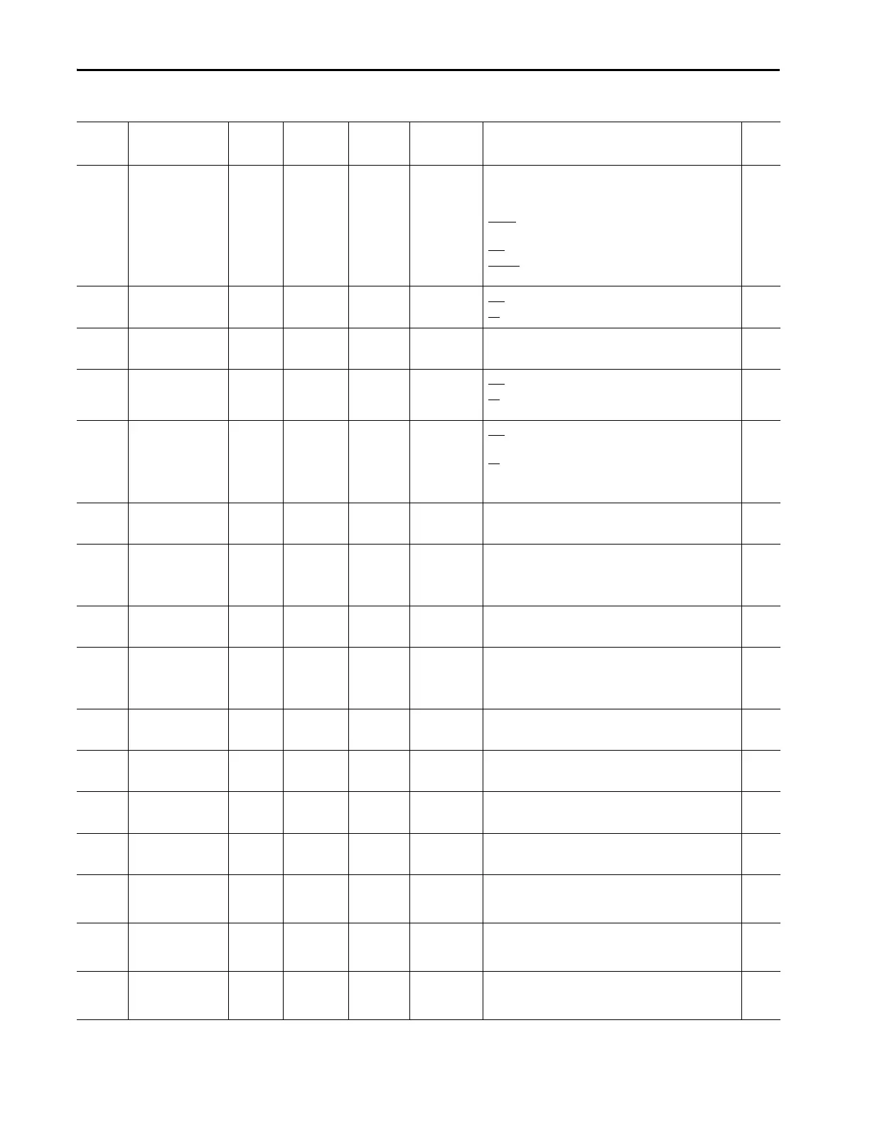
Table 67 - 150-SM2 Option Card Parameters
Number Name Unit Min/Max Default Enum Text Description Read/
Write
SM2.01
(GF)
Module Status 0/7 7 [Ready]
[PTC]
[CT Loss]
Displays information about the operational status of the 150-
SM2 PTC, Ground Fault, and External Current Transformer (CT)
Option Module.
Ready
: Bit 0 = Ready; Bit Set =1 indicates the module is ready
for operation.
PTC: Bit 1 = PTC; 1 = PTC Indicating Fault 0; = No fault
CT Loss: Bit 2 = CT Loss; 1 = CT disconnected; 0 = CT
Connected
R
SM2.02
(GF)
Fault Enable 0/3 0 PTC
Ground Fault
PTC: 0 = PTC Fault Disabled; 1 = PTC Fault Enabled
GF: 0 = Ground Fault Disabled; 1 = Ground Fault Enabled
R/W
SM2.02
(GF)
Fault Enable
(Refer to SM2.2)
SM2.03
(GF)
Alarm Enable 0/3 0 PTC
Ground Fault
PTC
: 0 = PTC Alarm Disabled; 1 = PTC Alarm Enabled
GF
: 0 = Ground Fault Alarm Disabled; 1 = Ground Fault Alarm
Enabled
R/W
SM2.04
(GF)
Restart Enable 0/3 0 PTC
Ground Fault
PTC
: 0 = does not restart after PTC Fault is cleared; 1 = restart
after PTC Fault is cleared
GF
: 0 = does not restart after the Ground Fault is cleared; 1 =
restart after the Ground Fault is cleared
R/W
SM2.05
(GF)
Turns Ratio :1 100/2000 1000 Enables user to configure the turns ratio for the GFCT being
used.
R/W
SM2.06
(GF)
Gnd Flt Level Amps 0/5 2.50 Enables the user to configure the level (value) of ground current
(primary current of GFCT) that determines a ground fault
condition.
R/W
SM2.07
(GF)
Gnd Flt Delay Secs 0.1/250 0.5 Sets the time limit that the ground fault level must be exceeded
before signalling a fault.
R/W
SM2.08
(GF)
Gnd Flt A Level Amps 0/5 2.50 Sets the level of ground current that determines a ground fault
alarm condition.
R/W
SM2.09
(GF)
Gnd Flt A Delay Secs 0.1/250 0.5 Sets the time limit that the ground fault level must be exceeded
before signalling an alarm.
R/W
SM2.10
(GF)
Gnd Flt Inh Time Secs 0/250 10.00 User configurable time delay to inhibit ground fault after a
start.
R/W
SM2.11
(GF)
Ground Current Amps 0/5 0.00 Measured ground current. R/W
SM2.12
(GF)
CT Enable 0/1 0 [Disable]
Enable
Disable/Enable CT Function. R/W
SM2.13
(GF)
CT Scaling A 0/5 0.01 Displayed result of the SMC-50 tuning feature determination of
the scaling between external CT and the internal current
measuring circuitry.
R
SM2.14
(GF)
CT Scaling B 0/5 0.01 Displayed result of the SMC-50 tuning feature determination of
the scaling between external CT and the internal current
measuring circuitry.
R
SM2.15
(GF)
CT Scaling C 0/5 0.01 Displayed result of the SMC-50 tuning feature determination of
the scaling between external CT and the internal current
measuring circuitry.
R

 Loading...


