4–4 Chapter 4: IP Core Architecture
Protocol Layers
Cyclone V Hard IP for PCI Express November 2011 Altera Corporation
■ Legacy interrupts—The
app_int_sts
input port controls legacy interrupt
generation. When
app_int_sts
is asserted, the Hard IP generates an
Assert_INT<n> message TLP. For more detailed information about interrupts,
refer to “Interrupt Signals for Endpoints” on page 5–17.
Protocol Layers
This section describes the Transaction Layer, Data Link Layer, and Physical Layer in
more detail.
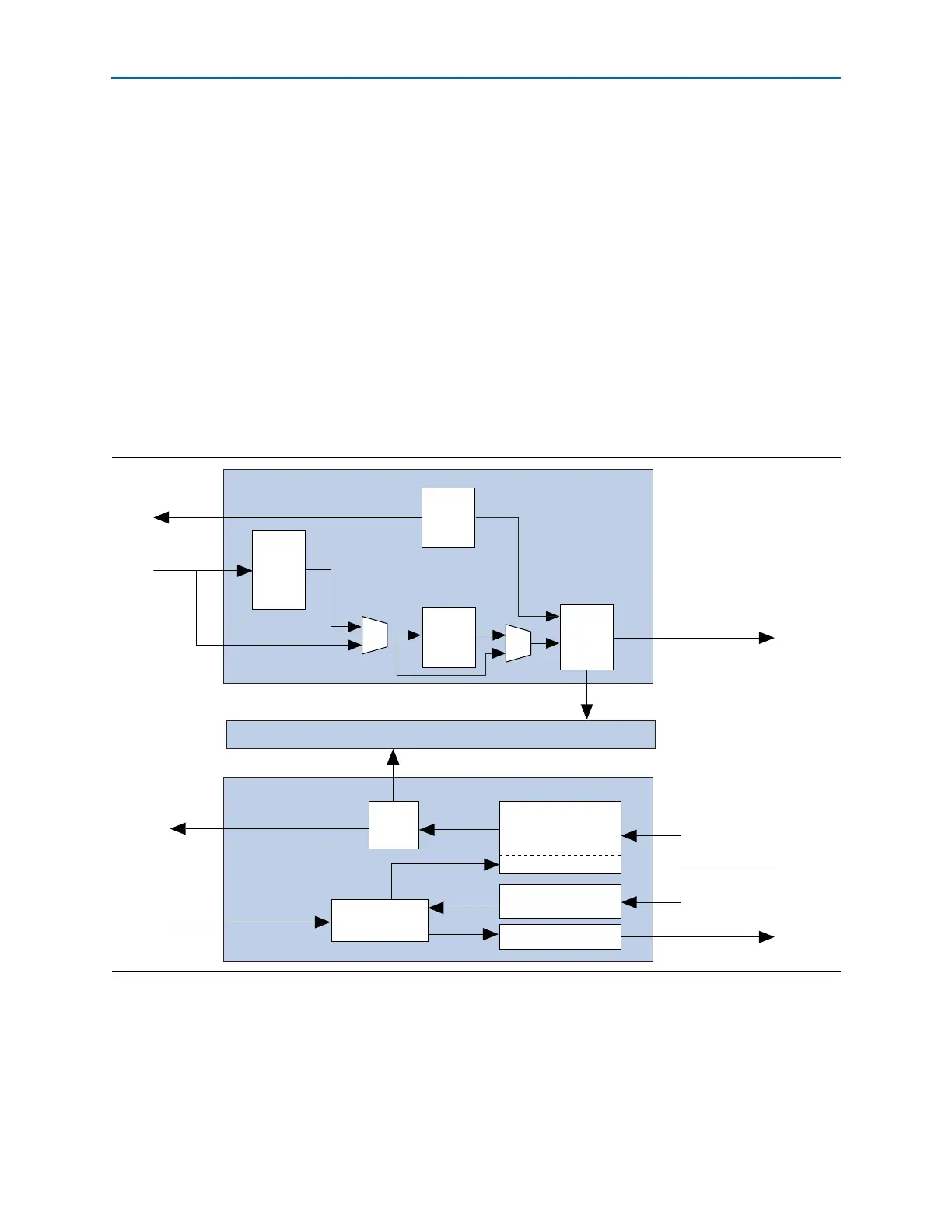
Transaction Layer
The Transaction Layer is located between the Application Layer and the Data Link
Layer. It generates and receives Transaction Layer Packets. Figure 4–2 illustrates the
Transaction Layer. As Figure 4–2 illustrates, the Transaction Layer includes three
sub-blocks: the TX datapath, the Configuration Space, and the RX datapath.
Tracing a transaction through the RX datapath includes the following steps:
1. The Transaction Layer receives a TLP from the Data Link Layer.
2. The Transaction Layer determines whether the TLP is well formed and directs the
packet based on traffic class (TC).
Figure 4–2. Architecture of the Transaction Layer: Dedicated Receive Buffer
Transaction Layer TX Datapath
Transaction Layer RX Datapath
Avalon-ST
RX Control
Configuration Space
TLPs to
Data Link Layer
RX Transaction
Layer Packet
Avalon-ST RX Data
Avalon-ST
TX Data
to Application Layer
Configuration Requests
Reordering
RX Buffer
Posted & Completion
Non-Posted
Flow Control Update
Transaction Layer
Packet FIFO
Width
Adapter
( <256
bits)
Packet
Alignment
TX
Control
RX
Control
TX Flow
Control