7–2 Chapter 7: Reset and Clocks
Clocks
Cyclone V Hard IP for PCI Express November 2011 Altera Corporation
■
npor
and
pin_perst
—These signals reset all sticky registers that may not be reset
in L2 low power mode or by the fundamental reset.
■
srst
—The
srst
signal initiates a synchronous reset of the datapath state
machines.
■
crst
—The
crst
signal initiates a synchronous reset of the nonsticky Configuration
Space registers.
1 The Cyclone V embedded reset sequence meets the 100 ms configuration time
specified in the PCI Express Base Specification 2.1.
Clocks
In accordance with the PCI Express Base Specification 2.1, you must provide a 100 MHz
reference clock that is connected directly to the transceiver. As a convenience, you
may also use a 125 MHz input reference clock as input to the TX PLL. The output of
the transceiver drives
coreclkout_hip
.
coreclkout_hip
must be connected back to
the
pld_clk
input clock, possibly through a clock distribution circuit required by the
specific application.
The Hard IP contains a clock domain crossing (CDC) synchronizer at the interface
between the PHY/MAC and the DLL layers which allows the Data Link and
Transaction Layers to run at frequencies independent of the PHY/MAC and provides
more flexibility for the user clock interface. Depending on system requirements, you
can use this additional flexibility to enhance performance by running at a higher
frequency for latency optimization or at a lower frequency to save power.
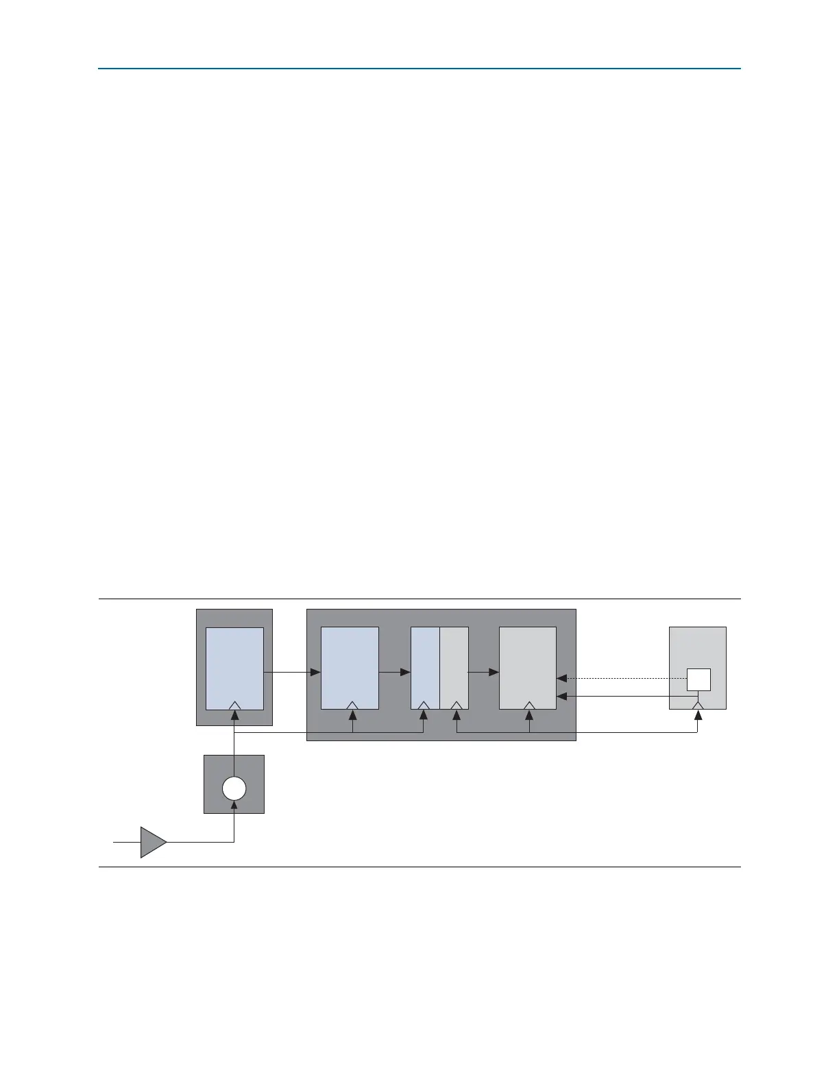
Figure 7–2 illustrates the clock domains.
Figure 7–2. Cyclone V Hard IP for PCI Express Clock Domains
100 MHz
(or 125 MHz)
refclk
Hard IP for PCI Express
PHY/MAC
Clock
Domain
Crossing
(CDC)
Data Link
and
Transaction
Layers
TX PLL
PCS
Transceiver
250 or 500 MHz
p_clk coreclk
coreclkout_hip
pld_clk (250 MHz)
Application
Layer
PLL
pld_clk (125 MHz)