Chapter 5: IP Core Interfaces 5–33
Physical Layer Interface Signals
November 2011 Altera Corporation Cyclone V Hard IP for PCI Express
User Guide
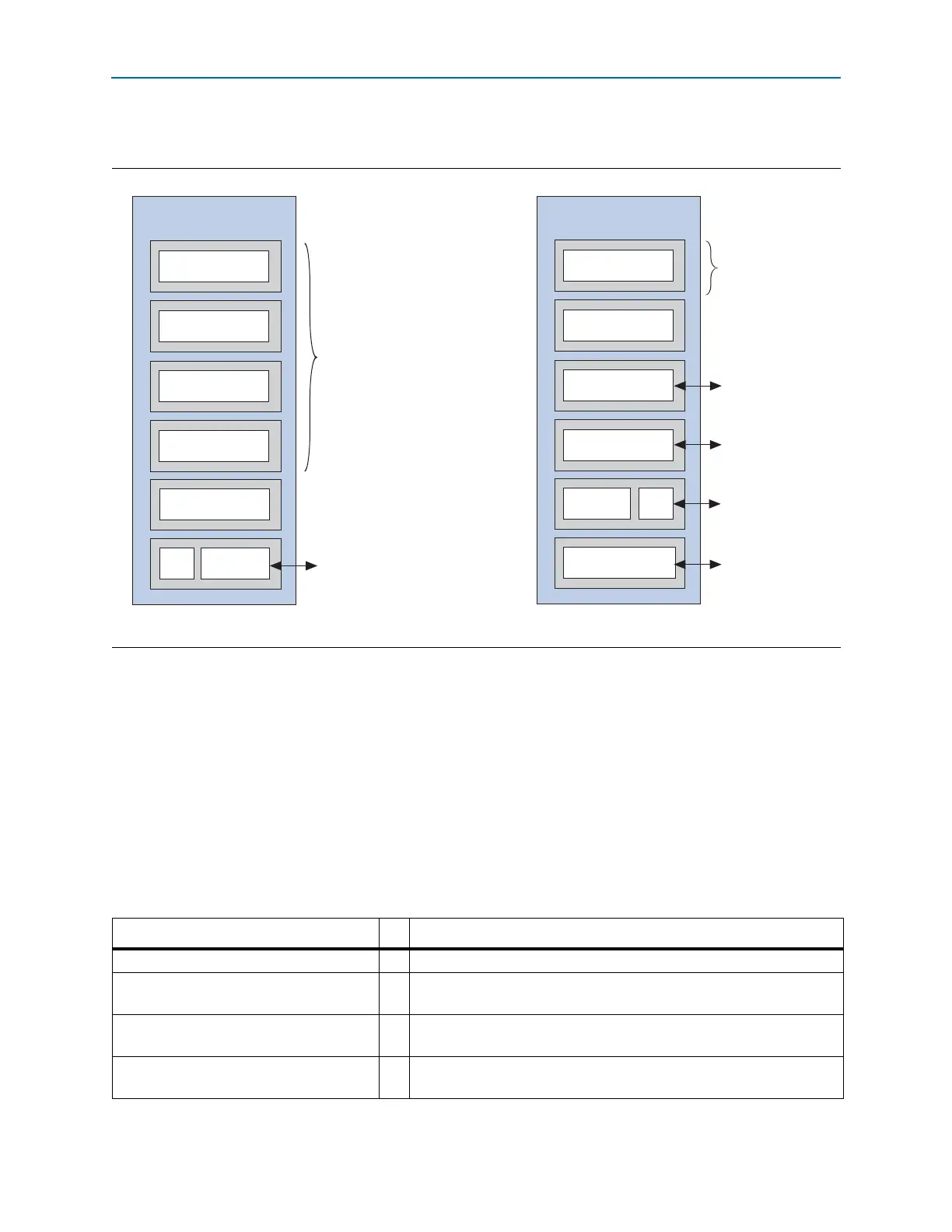
Figure 5–20 shows the channel placement for ×1 and ×4 variants.
PIPE Interface Signals
The PIPE signals are available so that you can simulate using either the one-bit or the
PIPE interface. Simulation is much faster using the PIPE interface. You can use the 8-
bit PIPE interface for simulation even though your actual design includes the serial
interface to the internal transceivers. However, it is not possible to use the Hard IP
PIPE interface in an actual device. Table 5–22 describes the PIPE interface signals used
for a standard 16-bit SDR or 8-bit SDR interface. In Table 5–22, signals that include
lane number 0 also exist for lanes 1-7. In Qsys, the signals that are part of the PIPE
interface have the prefix, hip_pipe. The signals which are included to simulate the PIPE
interface have the prefix, hip_pipe_sim_pipe.
Figure 5–20. Channel Placement for ×1 and ×4 Variants
x1
Transceiver Bank
LCD
LCD = Local Clock Divider
Channel 0 -
Data
Channel 1 - CMU PLL
Channel 2 - Data
Channel 4
Channel 5
PCI Express Lane 0
Channel 3
x4
Channel 0 - Data
Other
Protocols
Other
Protocols
Channel 1
Data
Channel 2 - Data
Channel 4 - CMU PLL
Channel 5
Channel 3 - Data
CCD
CCD = Central Clock Divider
Transceiver Bank
PCI Express Lane 0
PCI Express Lane 1
PCI Express Lane 2
PCI Express Lane 3
Table 5–22. PIPE Interface Signals (Part 1 of 3)
Signal I/O Description
txdata0[15:0]
O Transmit data
<
n>. This bus transmits data on lane
<
n>.
txdatak0[1:0]
(1)
O
Transmit data control
<
n>. This signal serves as the control bit for
txdata<
n>.
txdetectrx0
(1)
O
Transmit detect receive
<
n>. This signal tells the PHY layer to start a
receive detection operation or to begin loopback.
txelecidle
(1)
O
Transmit electrical idle
<
n>. This signal forces the TX output to electrical
idle.