5-2
P129390-106 Operator Manual Component Identification
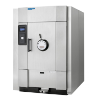
5.1 General Use this manual to become familiar with control locations and
functions before operating the sterilizer (refer to Figure 5-1 through
Figure 5-16). The controls for this sterilizer are contained within the
control touch screen. Control touch pads appear on the screen as
needed during each operation. Available controls change as the
sterilizer steps through different operations.
5.2 Main Sterilizer and
Cycle Controls
• Steam Supply Valve – This is located behind the side access
panel (or within the wall enclosure), on the plumbing skid. Refer
to Figure 5-1. Ensure this is in the open position before trying to
operate the sterilizer.
• Water Supply Valve – This is located behind the side access
panel (or within the wall enclosure), on the plumbing skid. Refer
to Figure 5-1. Ensure this is in the open position before trying to
operate the sterilizer.
• Air Supply Valve – This is located behind the side access panel
(or within the wall enclosure), on the plumbing skid. Refer to
Figure 5-1. Ensure this is in the open position before trying to
operate the sterilizer.
• Sterilizer Control Touch Screen – This is visible on the control
touch screen whenever the sterilizer is in Standby mode. Refer to
Figure 5-1.
The sterilizer enters operating mode by touching the control
screen surface anywhere. The control reverts to standby if the
control screen is not touched for five minutes.
NOTE: Touch-screen buttons respond to very slight pressure,
and only need to be pressed lightly.
• Emergency Stop Switch (with Key) – Located on the front
panel, below the sterilizer control touch pad. Shuts off all outputs
on the sterilizer; the key is used to reset the switch following
actuation. This key is to be retained by the supervisor.
• Control Power Switch (with key): Located on the front panel
below the emergency stop switch. This switch sequentially
powers up or power down the control system. Under normal
operating conditions this switch is left in the ON position at all
times.