BERT ThresholdBERT Threshold
MonitoringMonitoring
Total FrameTotal Frame
DifferenceDifference
6. Select a bit rate used for the measurement
(In the Port Setup dialog box, select ForcedForced or AutonegotiateAutonegotiate, not OffOff.)
7. On Test Setup page, touch Stream - Meas.Stream - Meas..
8. Select the JitterJitter and LatencyLatency check boxes.
9. Set Source of Latency / Jitter timestamp to GPSGPS.
Wait until the indicator on the right turns green.
10. Set Source of Latency / Jitter timestamp to InternalInternal.
Wait until the indicator on the right turns green.
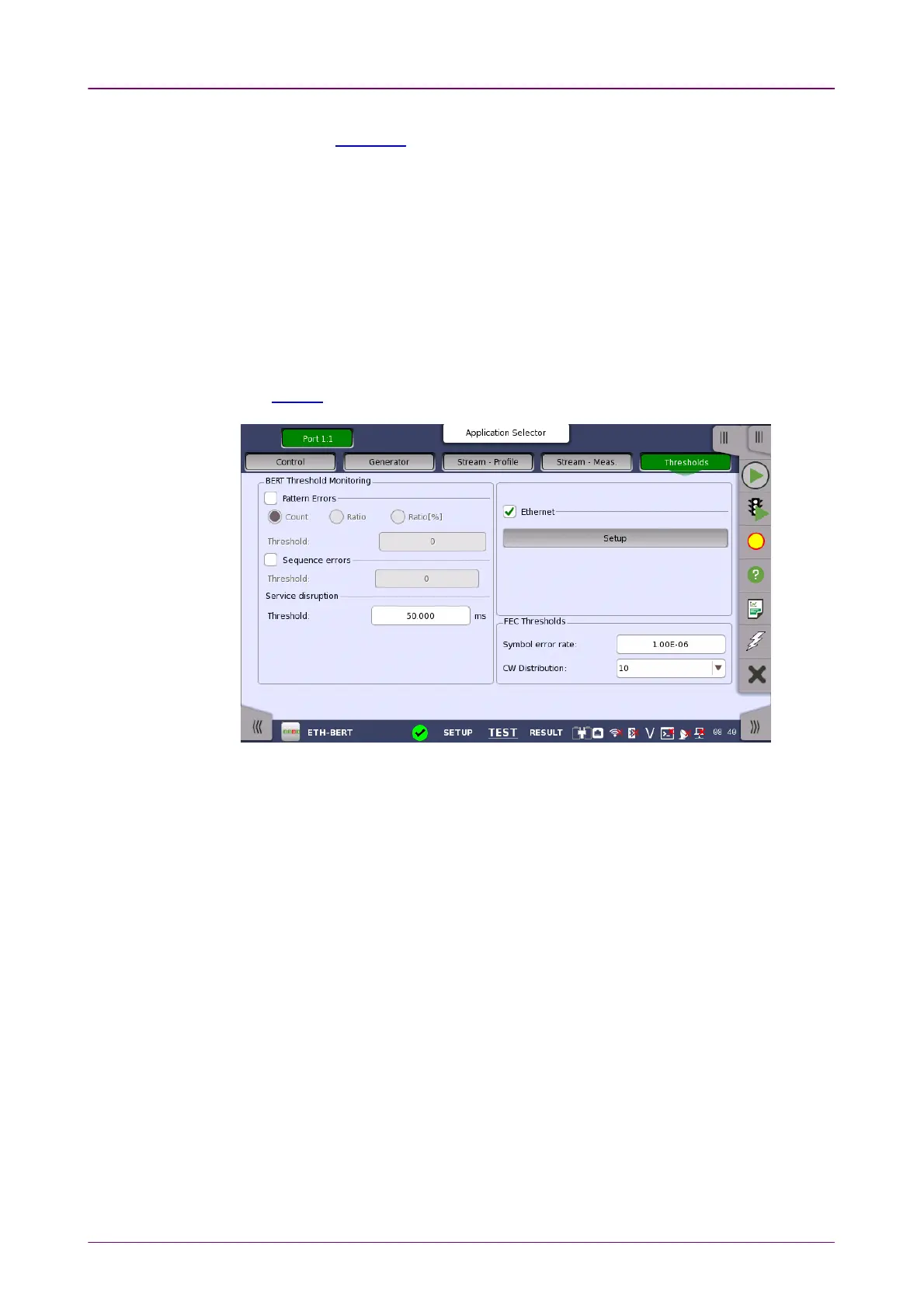
66..22..22..55 ThresholdsThresholds
Touching the ThresholdsThresholds button in the navigation area displays the following
screen.
The FollowFollow button appears when the Port 2 settings can follow Port 1.
This screen contains the parameters for setting up the various threshold values
(i.e. limits) for errors and Pass/Fail status that are used during the monitoring.
Pattern ErrorsPattern Errors
Allows you to enable monitoring of pattern errors (i.e. bit errors) and to set up
a threshold value for the bit error ratio.
Choose whether the threshold is specified as an absolute value or a percentage,
using the CountCount, RatioRatio and Ratio (%)Ratio (%) radio buttons, and then specify the value
in the ThresholdThreshold field.
Sequence errorsSequence errors
Allows you to enable monitoring of sequence errors and to set up the relevant
threshold value.
Service disruptionService disruption
If you specify a threshold value for the service disruptions (using the ThresholdThreshold
field), any disruption whose maximum duration time exceeds the threshold
value will be marked in red on the Test Result screen.
Allows you to select the reference port to measure the differential time, using
Difference from:Difference from: drop down menu.