Chapter 3 Panel Layout and Connectors
3-2
3.1 Panel Layout
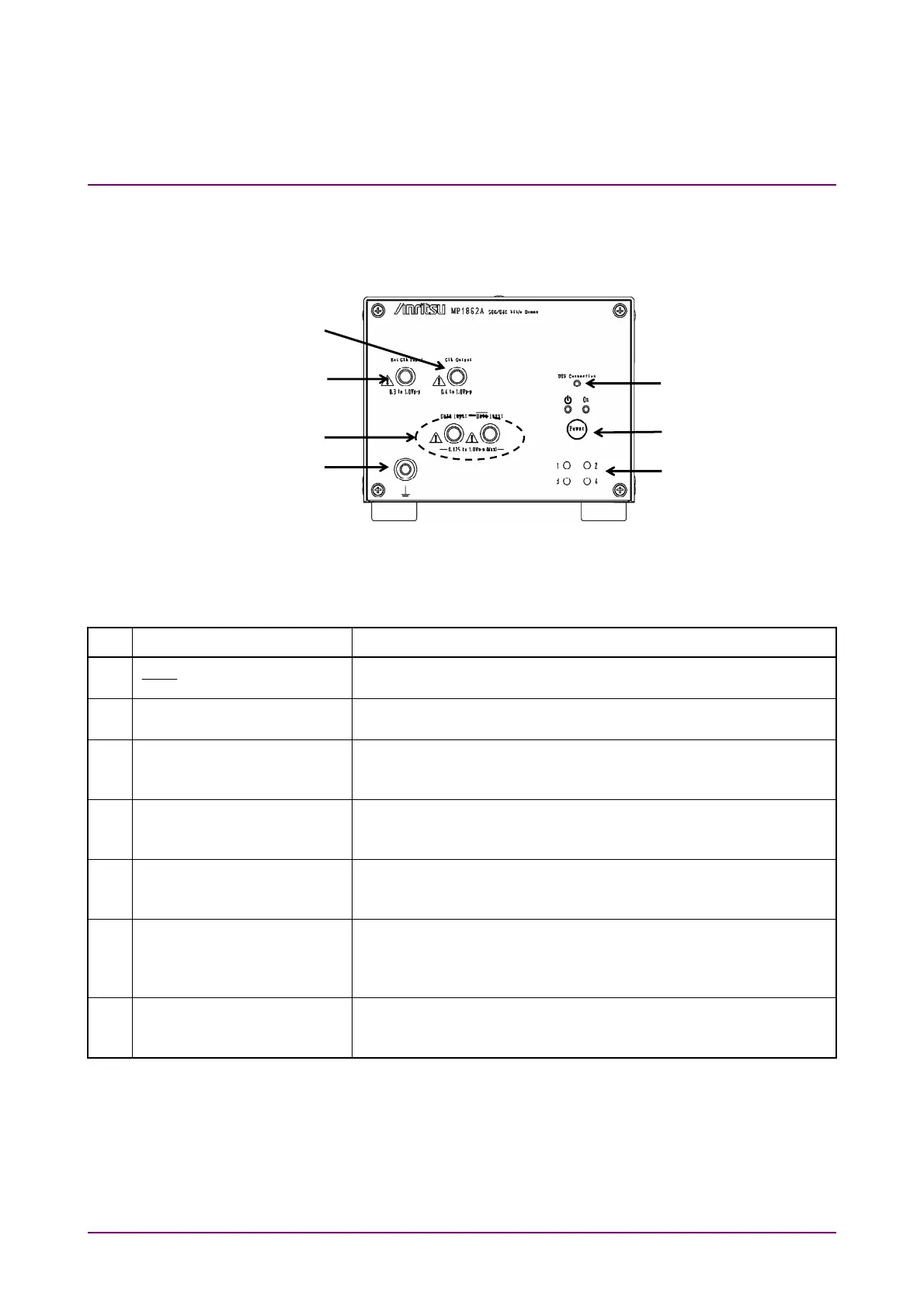
3.1.1 MP1862A Front Panel
Figure 3.1.1-1 MP1862A Front Panel
Table 3.1.1-1 MP1862A Front Panel Name and Function
No. Name Description
[1] Data Input connectors
Data
Input connectors
Connectors for inputting differential data signals.
Support both differential and single-ended input signals.
[2] Ext. Clock Input connector Connectors for inputting clock signal used as reference for
equipment operation
[3] Clock Output connector Connector for outputting the same frequency clock as the clock
that is input to the Ext. Clock Input connector. Terminate into
50
when not in use.
[4] USB Connection LED Displays status of connection between MP1862A and MP1800A
or control PC
The LED is lit when the MP1862A can be controlled.
[5] Power Switch Switches from ON to Standby
When AC adapter and power code are connected, the switch LED
lights orange in the Standby status and green at ON.
[6] Channel number indicators
(LEDs)
The lamp of the set channel number illuminates.
1: Blue, 2: Pink, 3: Purple, 4: Orange
Set the channel number with the Channel Setting switch on the
rear panel of MP1862A.
[7] Frame ground To which connects a wrist strap for antistatic measures before
using MP1862A.
Always wear the wrist strap when using MP1862A.
[1]
[2]
[7]
[3]
[6]
[5]
[4]