Chapter 4 Window Operations
4-18
4.4.2 When inputting jitter-modulated signals
•
When executing jitter tolerance test, etc. by inputting jitter-modulated
clock, set
of Delay to
to avoid malfunction of Delay
caused by excess jitter modulation. (Refer to
Figure 4.4.2-1.) When
using the MU181000A/B (with Option 001 Jitter Modulation) or
MU181500B, set
of Delay to
, and then set
of the MU181000A/B or MU181500B to
.
•
When executing Calibration of Delay, set jitter modulation of input
signal to non-modulation.
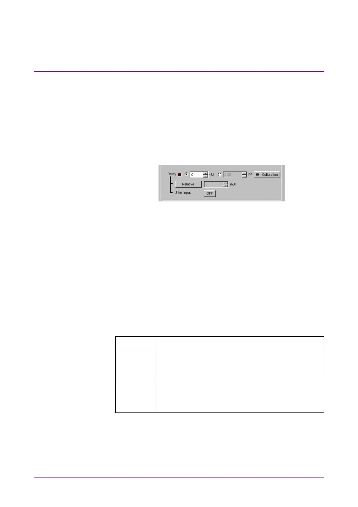
Figure 4.4.2-1 Clock delay setting items
Notes:
•
When jitter-modulated clock is input while
of Delay
is set to
the phase may become unstable.
•
The Delay lamp may light up when a jitter-modulated clock
signal is input. In addition, phase setting error may increase.
•
The Delay function has feedback process to improve its setting
accuracy at default setting (
is set to
.).
However, if
is set to
, the setting accuracy is
lowered because the feedback process is stopped.
Table 4.4.2-1 Jitter Input setting and use
Jitter Input Use
Jitter Tolerance Measurement
BER measurement when jitter amount applied to clock
signal is big.
(Delay is unstable when Jitter Input is OFF.)
Eye Margin measurement,
Eye Diagram measurement,
Bathtub measurement