3.1 Panel Layout
3-3
3
Panel Layout and Connectors
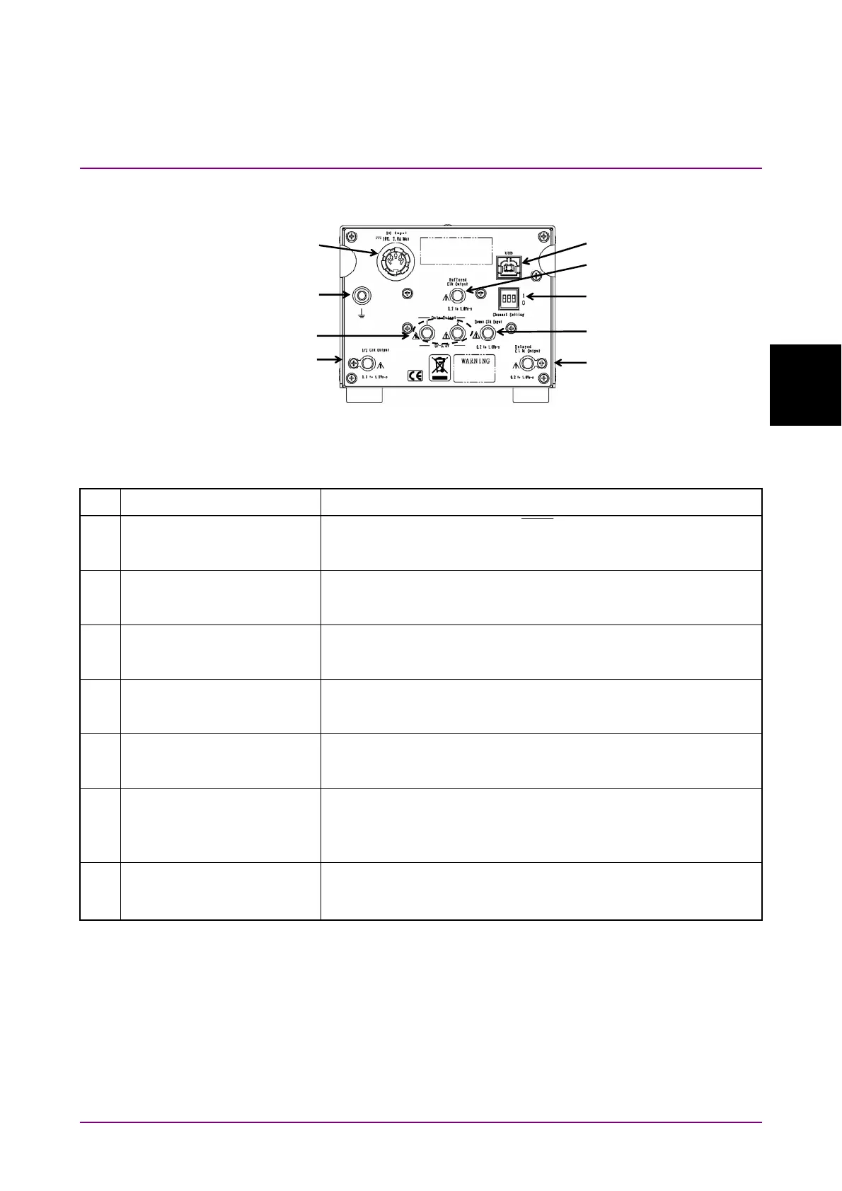
3.1.2 MP1862A Rear Panel
Figure 3.1.2-1 MP1862A Rear Panel
Table 3.1.2-1 MP1862A Rear Panel Name and Function
No. Name Description
[1] Data Output 1 connectors
Data Output 2 connectors
Outputs for 1:2 divided Data/
Data
Input signals
Connector for outputting data signals to the system
MU18304xA/B.
[2] Delayed Clock Output
connector
Connector for outputting the clock signal that is half of frequency
of the operating bit rate. Connect to the Demux Clock Input
connector using the supplied J1654A U-link cable B.
[3] Buffered Clock Output
connector
Connector for outputting the same frequency clock as the clock
that is input to the Ext. Clock Input connector. Terminate into
50
when not in use.
[4] 1/2 Clock Output connector Connector for outputting the clock signal (reference clock for
MU18304xA/B) that is half of the frequency clock output to the
Delayed Clock Output connector.
[5] Demux Clock Input
connector
Connector for inputting the clock signal that is half of frequency
of the operating bit rate. Connect to the Delayed Clock Output
connector using the supplied J1654A U-link cable B.
[6] DC Input connectors Connector for connecting AC adapter supplied as standard
accessory
Do not use non-Anritsu AC adapters, otherwise there is a risk of
damage to the equipment.
[7] USB port Used for connecting MP1800A or controller PC to this equipment
Do NOT connect anything other than the MP1800A or controller
PC.
[1]
[7]
[9]
[2]
[5]
[4]
[6]
[3]
[8]