4.8 Eye Diagram Measurement
4-23
4
4.8 Eye Diagram Measurement
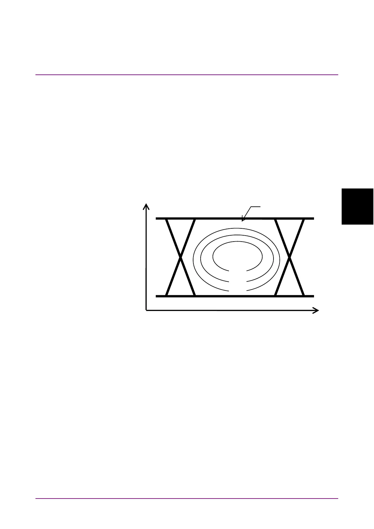
An eye diagram is a means for measuring digital signal quality. It
visualizes an open-eye margin two-dimensionally.
For example, an eye diagram measurement can be used when it is
required to measure the margin in the setting range for the threshold
voltage and clock phase of a decision circuit, while quality with an error
rate of E
−
12 or lower should be secured. In this event, a contour at an
error rate of E
−
12 measured with eye diagram measurement can be
obtained as a result. The required quality can be secured in the area
inside the contour. Therefore, the wider this area, the higher the signal
quality.
Figure 4.8-1 Schematic Diagram of Eye Diagram Measurement
The Eye Diagram measurement for 64 Gbit/s input data is available only
when all of the following conditions are met:
•
MP1862A is connected to MP1800A to which MU183040A/B or
MU183041A/B is installed.
•
MU18304xA/B is in the 2ch Combination state.
•
The
button is on.
To use the Eye Diagram measurement function, click the
module function button, and then select
. See
the
MX180000A Signal Quality Analyzer Control Software Operation
Manual
for details.