Chapter 4 Window Operations
4-4
4.2 Configuration of the Operation Window
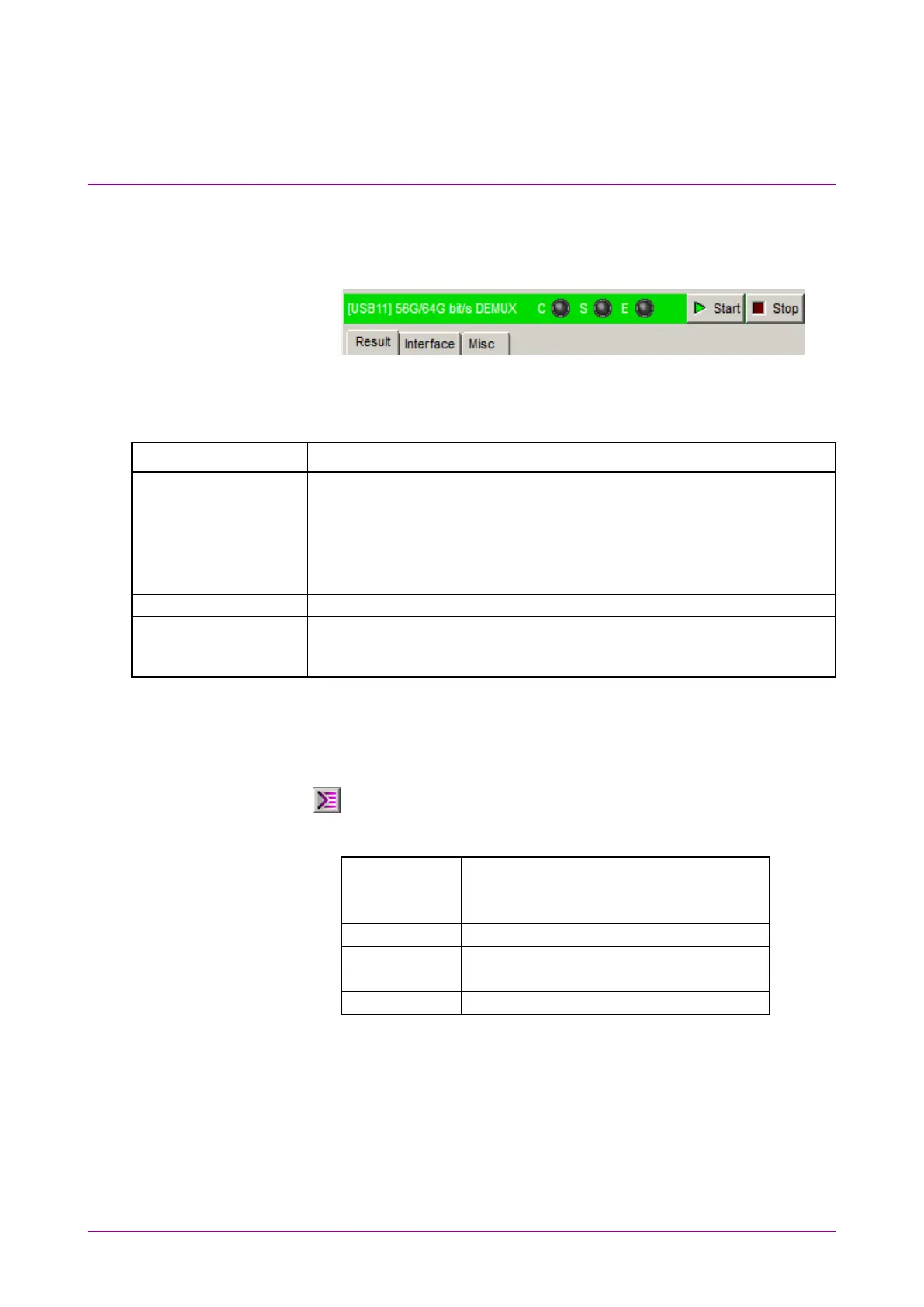
This section describes the tabs of the operation window for MP1862A.
Figure 4.2-1 Function Setting Selection Tabs
Table 4.2-1 Function Setting Selection Tabs
Tab name Function
Measurement results are displayed.
Tab is displayed when the MP1862A and either the MU18304xA or the
MU18304xB are installed in the same main frame and 4 ch
Combination is executed.
In addition to the above conditions, the measurement result is
displayed when the DEMUX-ED Link button is on.
This sets the Data/Clock input interface.
Sets whether to operate linked with the MU18304xA/B 32G ED and
opens the configuration dialog box for the ED you want to operate
Up to 4 MP1862As (CH1 to CH4) can be controlled by using one
MP1800A or control PC. The operation window can be toggled one after
another (CH1 to CH4) by repeatedly clicking the
button
(
).
Table 4.2-2 Channel Numbers and Title-Bar Names
Channel
Number of
MP1862A
Name on Title Bar
[USB11] 56G/64G bit/s DEMUX
[USB12] 56G/64G bit/s DEMUX
[USB13] 56G/64G bit/s DEMUX
[USB14] 56G/64G bit/s DEMUX