Spectrum Analyzer Performance Verification 3-9 Amplitude Accuracy
Model MS20xxB MM PN: 10580-00303 Rev. D 3-21
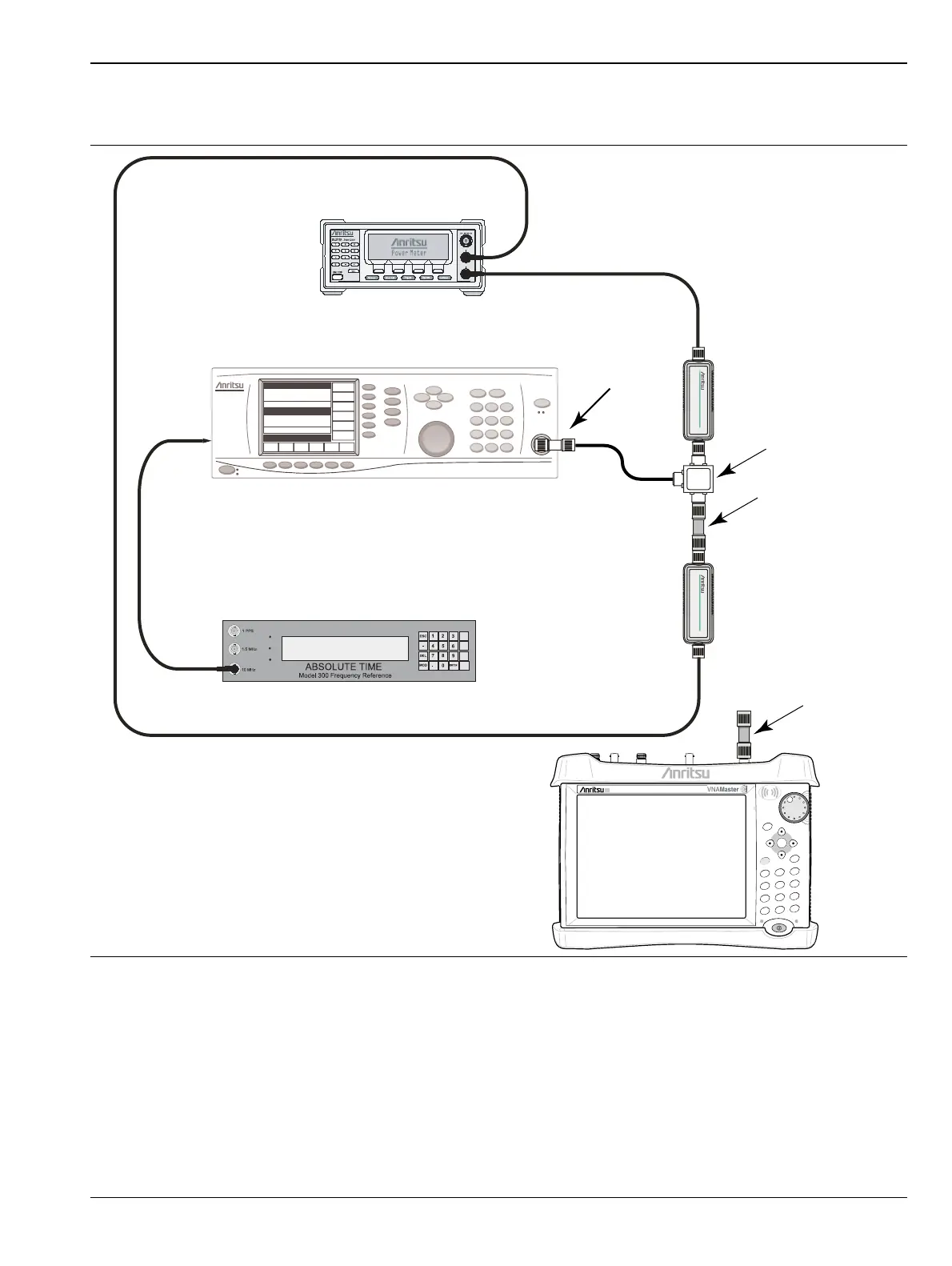
6. Install the 10 dB Fixed Attenuator to the other Power Splitter output and then connect Sensor A to the
end of the attenuator as shown in Figure 3-4.
7. Set the MG3692X to a frequency of 50 MHz.
8. Starting with 0 dBm, adjust the power level of the MG3692X to get a reading on Sensor A that matches
the power level into the Test Power Level @ 50 MHz columns of the following tables in Appendix A.
• MS2034B – Table A-17, “Spectrum Analyzer 50 MHz Amplitude Accuracy Setup Table”
on page A-8
• MS2035B – Table A-42, “Spectrum Analyzer 50 MHz Amplitude Accuracy Setup Table”
on page A-21
Figure 3-4. Absolute Amplitude Accuracy Verification Pretest Setup
Attenuator
Adapter
10 MHz Reference
Signal Source
Power Meter
Sensor B
Power Splitter
VNA Master
Power Charge
+/-
.
0
3
Sweep
2
Calibrate
1
Preset
6
Limit
5
Trace
4
Measure
9
Mode
8
System
7
File
Shift
Back
Enter
ESC
Adapter
Sensor A

 Loading...


